


surface before use. Failure to do so could cause
the router table to tip over or slide, resulting in
property damage and/or serious personal injury.
1. Set the router table on a workbench or other stable
and sturdy surface.
2, While holding the router table in place, spot the loca-
tion of the two mounting holes in each of the legs onto
the workbench. (Total number of holes is four)
3. Remove the router table from the workbench and
set it aside.
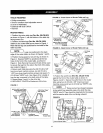
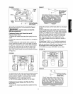
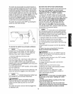
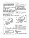
FIGURE 21
Router
Table
Leg
Work Surface/Table
Mounting
Holes/
Foot Boss
4. Drill a 5/32" diameter hole at each of the spotted
hole locations.
5. Position the router table on the workbench so that
the holes in the legs line up with the drilled holes in the
workbench.
6. Secure the router table to the workbench using the
four #12 x 1-3/4" long round head wood screws (not pro-
vided). Applying a little soap to the screw threads will
make it easier to thread the screws into the drilled holes.
7. TIGHTEN the screws SECURELY.
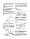
ALTERNATE METHOD
1. Cut a board 18-1/4" wide by 24" long from a piece of
3/4" thick wood.
2, Place the router table on the board so that the spac-
ing from the edge of the board to the router table legs
is equal on all four sides of the board.
3. While holding the router table in place, spot the loca-
tion of the two mounting holes in each of the legs onto
the board. (Total number of holes is four)
4. Remove the router table from the board and set it
aside.
5. Drill a 5/32" diameter hole at each of the spotted
hole locations.
6. Position the router table on the board so that the holes
in the legs line up with the drilled holes in the board.
7. Secure the router table to the board using four #12 x
1-3/4" long round head wood screws (not provided).
Applying a little soap to the screw threads will make it
easier to thread the screws into the drilled holes.
8. TIGHTEN the screws SECURELY.
9. Place the router table on a workbench or other sta-
ble and sturdy surface, and firmly secure the board
with screws or other suitable means.
m
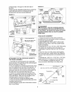
I NOTE I The specially designed legs with
I
foot boss may be clamped to a workbench or work
surface. Always make sure the clamps are tight
before and after using the router.
SELECTING AND INSTALLING THE ROUTER
TABLE INSERTS
This router table comes with three tabletop inserts in
the following hole sizes:
• 1-1/4" diameter, for use with router bits with diame-
ters up to 1-1/8"
• 1-7/8" diameter, for use with router bits with diame-
ters up to 1-3/4"
• 2-1/8" diameter, for use with router bits with diame-
ters up to 2"
• For router bits with diameters between 2" and 2-3/4",
do not use a table top insert.
I _'WARNINGI A 2-3/4" Diameter router bit is
the LARGEST router bit that can be used on this
router table.
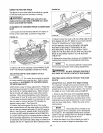
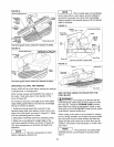
1. Select the tabletop insert that accommodates the
router bit to be used.
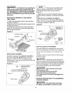
2. Assemble the insert to the tabletop by pressing it
into the large hole in the top of the router table, as
shown in Figure 22.
3. Press down equally over the tabs on the insert, so
that the tabs snap into place.
4. To remove, insert a finger in the insert hole and gen-
tly pull up until the tabs disengage the hole. When not
in use, store the inserts in a convenient place.
I _WARNINGI DO NOT attempt to remove table
top inserts from the tabletop unless the router bit
has been removed from the router, and the router
is unplugged.
FIGURE 22
Router Table,
Fence_ /, _, -- ,\ ,
11