


USING THE ROUTER TABLE
The fence on your router table is provided as a guide
to hold the work piece for accuracy in routing.
I_I_WARNING] BEFORE each and every use,
make sure the router table is SECURE on a work-
bench and DOES NOT MOVE.
ALIGNMENT OF UNITIZED FENCE TO MITER BAR
SLOT
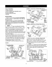
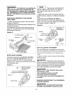
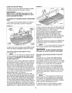
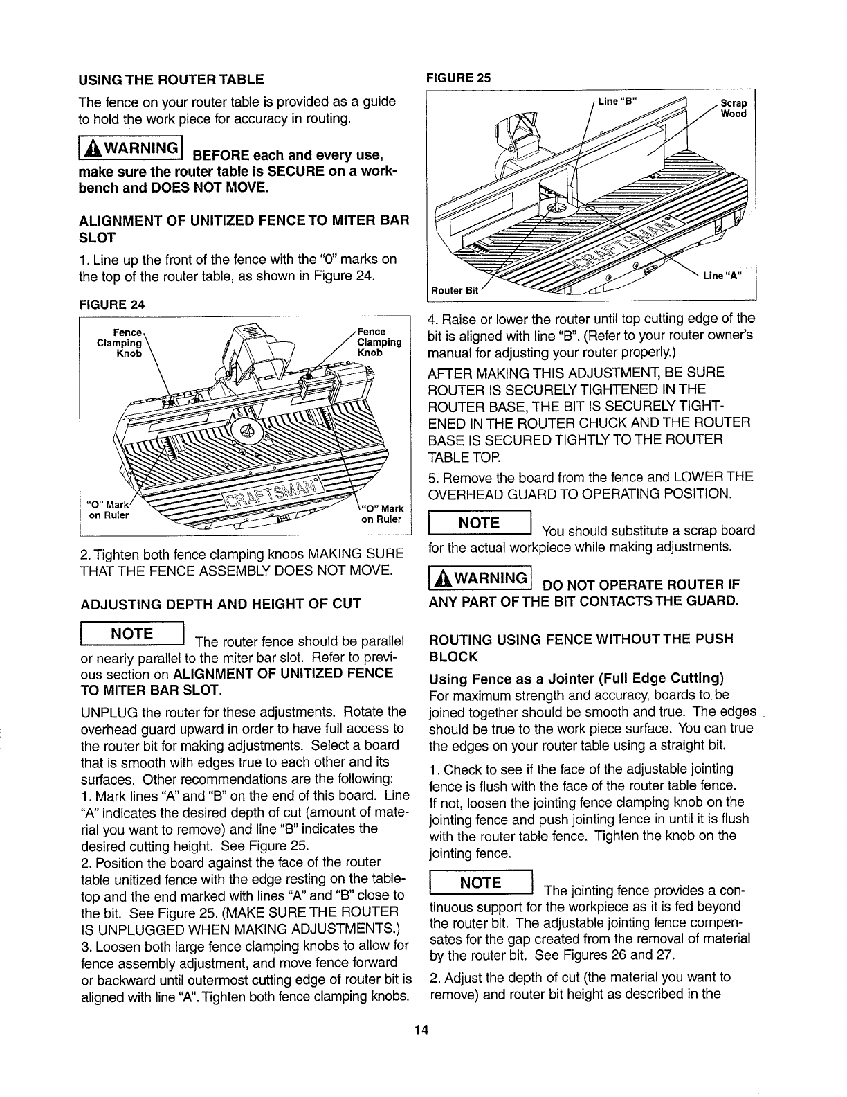
1. Line up the front of the fence with the "0" marks on
the top of the router table, as shown in Figure 24.
FIGURE 24
Fence \
Clamping \
"O" M_
on Ruler
2. Tighten both fence clamping knobs MAKING SURE
THAT THE FENCE ASSEMBLY DOES NOT MOVE.
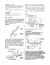
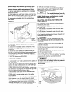
"IGURE 25
Line "B" Scrap
Wood
Router Bit
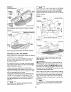
_Fence 4. Raise or lower the router until top cutting edge of the
Clamping bit is aligned with line "B". (Refer to your router owner's
manual for adjusting your router properly.)
AFTER MAKING THIS ADJUSTMENT, BE SURE
ROUTER IS SECURELY TIGHTENED IN THE
ROUTER BASE, THE BIT IS SECURELY TIGHT-
ENED IN THE ROUTER CHUCK AND THE ROUTER
BASE IS SECURED TIGHTLY TO THE ROUTER
TABLE TOR
5. Remove the board from the fence and LOWER THE
OVERHEAD GUARD TO OPERATING POSITION.
"'_'°OnRMu_rk I NOTE I YOUshou!d substitute a scrap board
for the actual workpiece while making adjustments.
ADJUSTING DEPTH AND HEIGHT OF CUT
I I The router fence should be parallel
I
NOTE
or nearly parallel to the miter bar slot. Refer to previ-
ous section on ALIGNMENT OF UNITIZED FENCE
TO MITER BAR SLOT.
UNPLUG the router for these adjustments. Rotate the
overhead guard upward in order to have full access to
the router bit for making adjustments. Select a board
that is smooth with edges true to each other and its
surfaces. Other recommendations are the following:
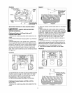
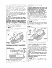
1. Mark lines "A" and "B" on the end of this board. Line
"A" indicates the desired depth of cut (amount of mate-
rial you want to remove) and line "B" indicates the
desired cutting height. See Figure 25.
2. Position the board against the face of the router
table unitized fence with the edge resting on the table-
top and the end marked with lines "A" and "B" close to
the bit. See Figure 25. (MAKE SURE THE ROUTER
IS UNPLUGGED WHEN MAKING ADJUSTMENTS.)
3. Loosen both large fence clamping knobs to allow for
fence assembly adjustment, and move fence forward
or backward until outermost cutting edge of router bit is
aligned with line "A". Tighten both fence clamping knobs.
I '_WARNINGI DO NOT OPERATE ROUTER IF
ANY PART OF THE BIT CONTACTS THE GUARD.
ROUTING USING FENCE WlTHOUTTHE PUSH
BLOCK
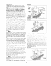
Using Fence as a Jointer (Full Edge Cutting)
For maximum strength and accuracy, boards to be
joined together should be smooth and true. The edges
should be true to the work piece surface. You can true
the edges on your router table using a straight bit.
1. Check to see if the face of the adjustable jointing
fence is flush with the face of the router table fence.
If not, loosen the jointing fence clamping knob on the
jointing fence and push jointing fence in until it is flush
with the router table fence. Tighten the knob on the
jointing fence.
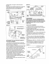
I NOTE I The jointing fence provides a con-
m
tinuous support for the workpiece as it is fed beyond
the router bit. The adjustable jointing fence compen-
sates for the gap created from the removal of material
by the router bit. See Figures 26 and 27.
2. Adjust the depth of cut (the material you want to
remove) and router bit height as described in the
14