


section ADJUSTING DEPTH AND HEIGHT OFTHE
CUT. Tightly secure the fence assembly and the router
as described before. (MAKE SURE ROUTER IS
UNPLUGGED WHEN MAKING ADJUSTMENTS.)
3. LOWER THE OVERHEAD GUARD to the operating
position. (Overhead guard shown raised for reasons
of clarity.)
4. Check you adjustments by turning the router "ON"
using the switch, and feed a piece of scrap wood a few
inches beyond the router bit. Then stop and turn the
router "OFF" using the switch.
I Feed work AGAINST the rotation
NOTE
of the cutter as shown by the direction arrow in Figures
26 and 27.
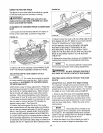
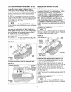
4. Loosen the adjustable jointing fence clamping knob
and move the jointing fence out, flush against the fin-
ished edge of the scrap wood, as shown in Figures 26
and 27. Retighten the adjustable jointing fence knob.
5. Repeat the test cut on the scrap wood.
6. The router table is now ready for use.
! I
i NOTE I For best results when jointing, take
very shallow cuts of 1/32" or less.
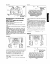
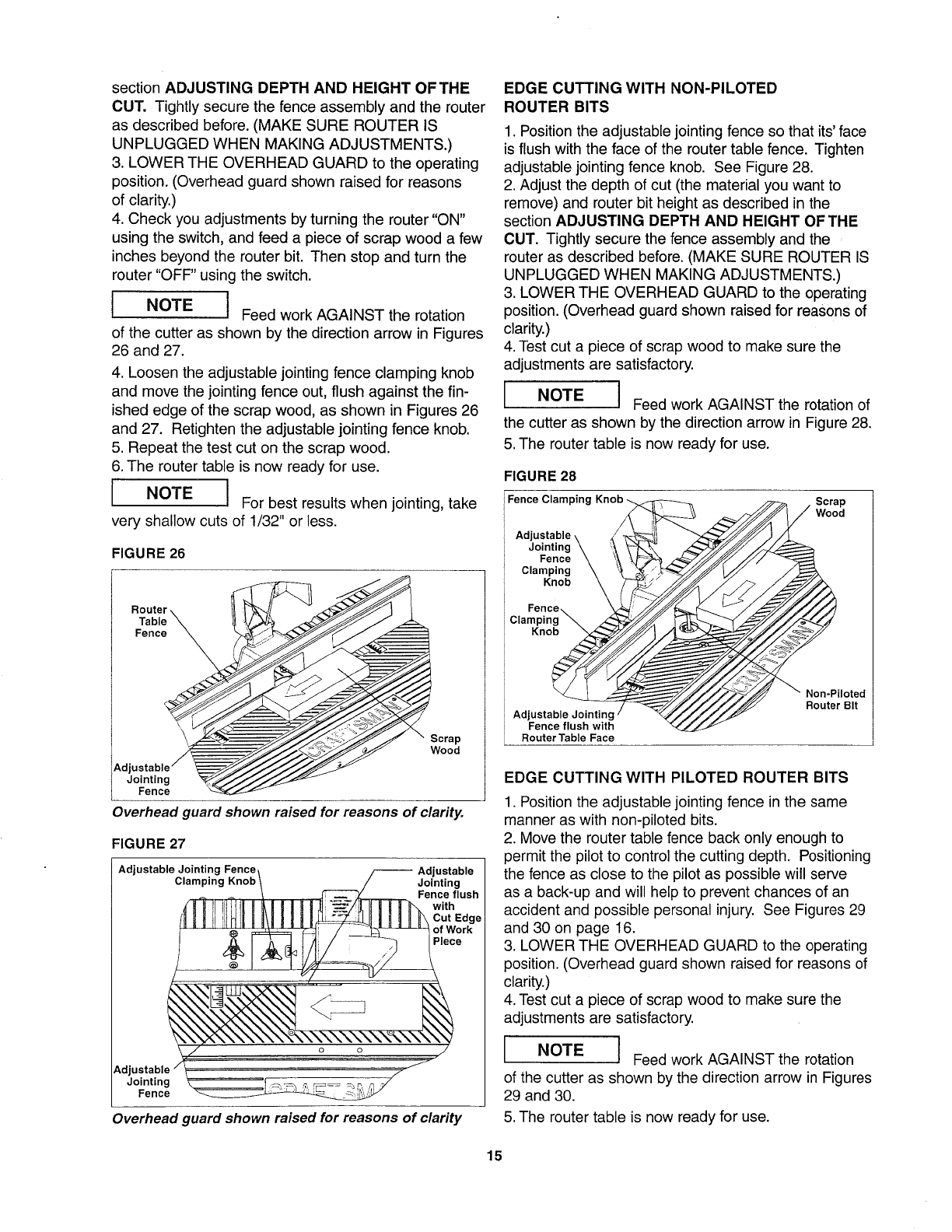
FIGURE 26
Wood
Adjustable _ _--//_//////_
Jointing _/_.J////_
Fence
Overhead guard shown raised for reasons of clarity.
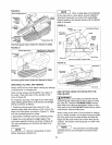
FIGURE 27
Adjustable Jointing Fence
Clamping
Jointing
Fence flush
with
Adjustable
Jointing
Fence
Overhead guard shown raised for reasons of clarity
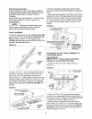
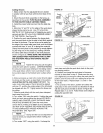
EDGE CUTTING WITH NON-PILOTED
ROUTER BITS
1. Position the adjustable jointing fence so that its' face
is flush with the face of the router table fence. Tighten
adjustable jointing fence knob. See Figure 28.
2. Adjust the depth of cut (the material you want to
remove) and router bit height as described in the
section ADJUSTING DEPTH AND HEIGHT OF THE
CUT. Tightly secure the fence assembly and the
router as described before. (MAKE SURE ROUTER IS
UNPLUGGED WHEN MAKING ADJUSTMENTS.)
3. LOWER THE OVERHEAD GUARD to the operating
position. (Overhead guard shown raised for reasons of
clarity.)
4. Test cut a piece of scrap wood to make sure the
adjustments are satisfactory.
=
I NOTE I Feed work AGAINST the rotation of
=
the cutter as shown by the direction arrow in Figure 28.
5. The router table is now ready for use.
FIGURE 28
Fence Clamping Knob _ Scrap
Wood
Adjustable \
Jointing \
Fence \
Clamping \
Knob _
Fence...
Clamping _ z_
Knob _
Non-Piloted
Adjustable Jointing ! Router Bit
Fence flush with
Router Table Face
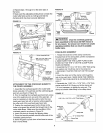
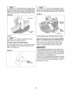
EDGE CUTTING WITH PILOTED ROUTER BITS
1. Position the adjustable jointing fence in the same
manner as with non-piloted bits.
2. Move the router table fence back only enough to
permit the pilot to control the cutting depth. Positioning
the fence as close to the pilot as possible will serve
as a back-up and will help to prevent chances of an
accident and possible personal injury. See Figures 29
and 30 on page 16.
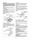
3. LOWER THE OVERHEAD GUARD to the operating
position. (Overhead guard shown raised for reasons of
clarity.)
4. Test cut a piece of scrap wood to make sure the
adjustments are satisfactory.
D
i NOTE I Feed work AGAINST the rotation
=
of the cutter as shown by the direction arrow in Figures
29 and 30.
5. The router table is now ready for use.
15