– 2 –
– 5 –
– 9 –
– 3 – – 4 –
– 6 –
– 10 –
– 7 –
– 11 –
– 8 –
– 12 –
Applications
General Leveling and Aligning
1. Place the laser on a flat surface. The laser must be level within its self-
leveling range.
2. Adjust the position of the Line or Point Beams so they are at the desired
positions.
3. Mark the position of the wall, elevation, floor or ceiling.
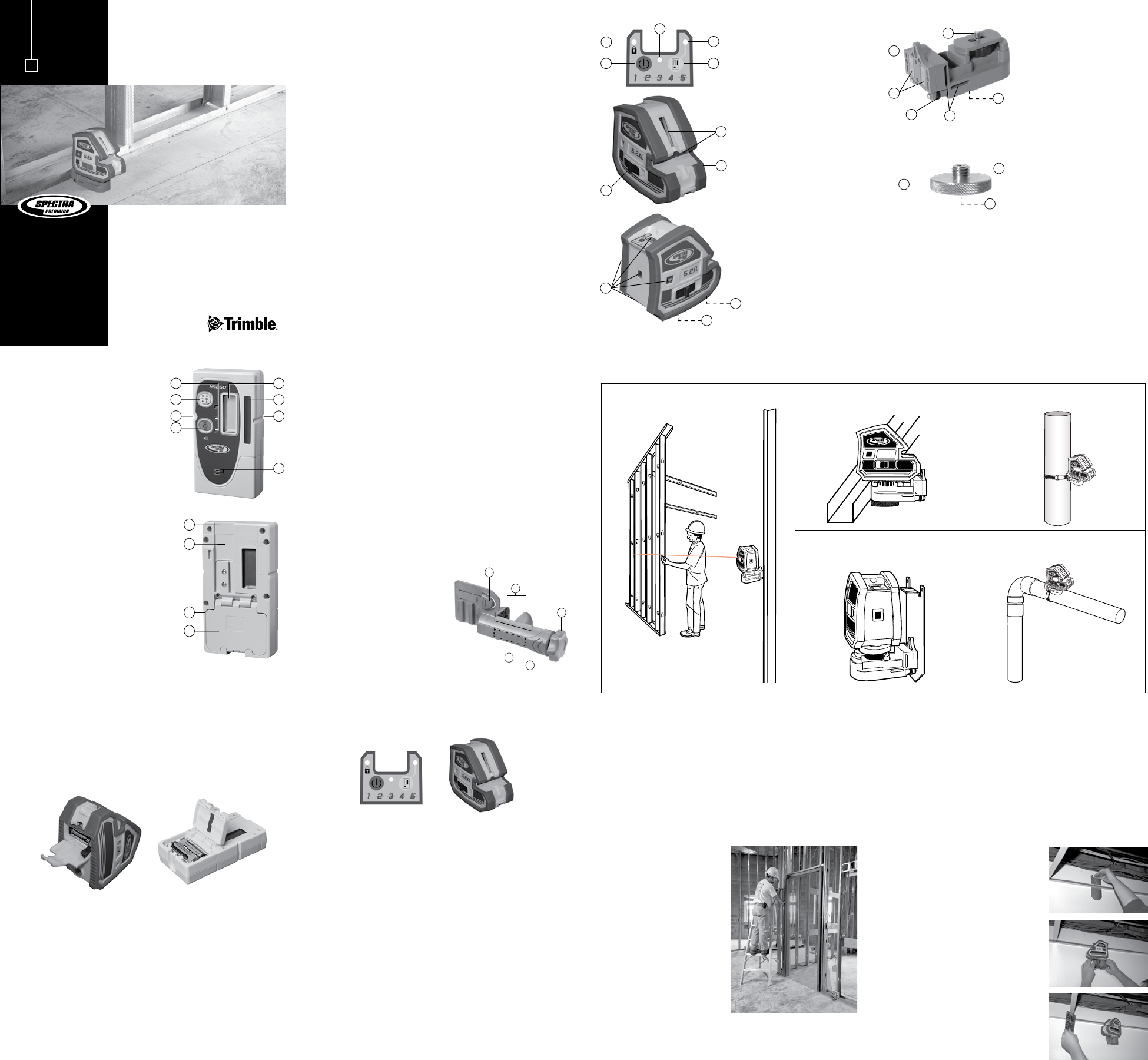
Installing and Plumbing a Wall
1. Place the laser so the Vertical Line
Beam is positioned over the desired
wall location (usually indicated by 2
floor marks).
NOTE: If the floor track is already
installed the laser should be placed
on the Universal Mount or
Universal Mount Adapter so the
Vertical Line can be positioned
over the edge of the track.
2. Use the Vertical Line Beam to
position the top track.
Batteries
Installation/Removal
CAUTION: The batteries should be removed when storing the laser more
than 30 days.
1. Release the battery door latch using your fingers, a coin, or a screwdriver.
Open the door.
2. Install/remove the AA batteries. Insert the positive (+) end first to ease
installation.
Note: When installing the batteries, be sure to note the positive (+) and
negative (–) diagrams molded on the battery housing.
3. Close the battery door and latch it shut.
Disposal
Some areas have regulations regarding the disposal of batteries. Be sure to
dispose of discharged batteries properly.
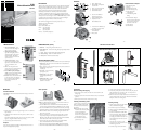
5.2XL
5-Point & CrossLine Laser
User Guide
www.trimble.com
•
2
4
Introduction
Thank you for choosing the Spectra Precision
®
Laser 5.2XL from the Trimble
®
family of precision products. This simple-to-use tool allows you to perform
leveling or vertical plumb work. You can also use the laser outdoors for
leveling and aligning applications (optional HR250 receiver required).
Before using the laser, be sure to read this operator’s manual carefully.
Included in it is information about setting up, using, and maintaining the
laser. Also included in this manual are CAUTIONS and Notes. Each of these
words represents a level or danger or concern. A CAUTION indicates a hazard
or unsafe practice that could result in
minor
injury or property damage. A
Note indicates important information unrelated to safety.
Your comments and suggestions are welcome; please contact us at:
Trimble Construction Tools Division
8261 State Route 235
Dayton, Ohio 45424 U.S.A.
Phone: (937) 245-5600
(800) 538-7800
FAX: (937) 233-9004
Internet: www.trimble.com/spectra
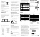
6. Laser Line Exit Windows -
Horizontal and Vertical
7. Protective Rubber Bumper
8. Compensator Lock /
Manual Mode Switch
0002-3420 Universal Mount
Features
1
3
5
1. Power / Mode button
2. Manual Mode / Compensator
Lock On LED
3. Power On / Low Battery LED
4. Receiver Mode On LED
5. Receiver Mode Button
6
7
8
9
9. Laser Pointer Exit Windows (5)
Left, Right, Up, Down, Front
10. 5/8x11 Thread and
1/4x20 Thread
11. Battery Door
10
11
HR250 Receiver
1. Power and Audio Button – turns
the receiver on/off and changes the
audio to loud, soft, and off.
2. Marking Notches (both sides) –
align with the on-grade portion of
the photocell and are used to mark
elevation readings. The marking
notches are 50 mm (2 in.) from the
top of the receiver.
3. Grade-Sensitivity Button— allows
you to select the receiver’s on-grade
sensitivities, which include fine: 1.5 mm
(
1
/16 in.) and medium: 3 mm
(
1
/8 in.).
4. LEDs – show the position of the
receiver relative to the laser beam (above
grade, on grade, or below grade).
5. Front and Back Liquid Crystal Displays
(LCDs) – show the power, audio, elevation,
grade sensitivity and battery status.
6. Photocell – detects the laser beam when
it strikes the receiver. If the photocell
does not detect the laser beam for 30
minutes, the receiver shuts off
automatically.
2
2
5
1
3
6
7
4
HR250 Receiver (cont.)
7. Audio Port – is the opening the sound comes out of.
8.
Clamp-Tab Recess
– is the area that the general-purpose clamp’s release
tab fits into.
9.
Label
– shows the serial number and manufacturing date.
10.
Battery Housing
– holds 2 AA alkaline batteries.
11.
Battery Door
– holds the batteries securely
8
9
10
11
General-Purpose Clamp
The C59 clamp allows the receiver to be attached to a survey rod or wooden pole.
1. Release Tab – allows the receiver to be locked onto or released from the
general-purpose clamp.
2. Jaws – close/open so that the general-purpose clamp can be attached to or
released from a survey rod or
wooden pole.
3. Jaws Screw – controls the closing/
opening of the jaws.
4. Reading Edge – aligns with the
receiver’s on-grade marking
notches.
5. Bubble Screw Holes – are where
the optional 1277-6251S rod
bubble kit is mounted.
1
3
2
5
4
Basic Operation
1. Unlock the laser’s compensator by sliding the switch to the LEFT.
NOTE: For added mechanism protection always lock the laser when not in
use by sliding the switch to the RIGHT.
2. Press the POWER button, the POWER LED illuminates GREEN. To
turn OFF the laser, PRESS & HOLD the POWER button for 3 seconds.
3. Each time the POWER button is pressed the laser beams will cycle through
the following sequence: H LineV LineHV Lines5 PointsAll Beams
4. When the unit is tilted out of its self-leveling range the laser beams will
blink 2 times per second.
5. The laser can be taken out of automatic self-leveling mode to perform
slope work by locking the laser’s compensator (slide the switch to the
RIGHT). In this mode the LOCK symbol LED will illuminate GREEN,
and the laser beams will flash 3 times every 30 seconds.
6. To operate the laser with the HR250 receiver press the RECEIVER
button. The RECEIVER LED will illuminate GREEN.
7. When the batteries need changed the POWER LED illuminates RED.
8. To turn OFF the laser, PRESS & HOLD the POWER button for 3 seconds.
Installing a Ceiling
1. Measure up from the floor (or other reference
mark) to the finished ceiling height.
2. Install the first piece of wall molding.
3. Slide the ceiling plate (0002-3480) behind
the wall molding.
4. Attach the Universal Mount (0002-3420)
and Universal Mount Adapter (0002-3430)
to the laser and magnetically attach it to
the ceiling plate so that the level beam is at
wall molding height. Install the rest of the
wall molding.
5. Lower the laser 5 cm (2.0 in.) on the
ceiling plate so that the level beam is at the
horizontal target elevation.
6. Install the ceiling’s cross Ts and main Ts.
3. Use the Vertical Line Beam to position the floor track.
4. To locate the plumb point over a wall corner or other point place the
Down Point Beam over the corner or mark. Use the Up Point to
determine the top track corner location.
NOTE: If the floor track is already installed use the Universal Mount to
position the Down Point over the corner. Add the Universal Mount
Adapter if tall floor track is being used.
Over Tall Floor Track or Obstacles
with
0002-3430 Universal Mount Adapter
Ceiling with 0002-3430 Universal Mount
Adapter and 0002-3480 Ceiling Plate
Columns with Mounting Strap
Pipes / Conduit
with
Mounting Strap
1 M (4 Ft) Marks
Universal Mount & Adapter
12. Nail Mounting Hole
13. Magnets
14. Fine Adjustment Knobs
15. Slots for Mounting Straps
16. 5/8x11 Thread and
1/4x20 Thread
17. 1/4x20 Mounting Knob -
Sliding
18. Universal Mount Adapter -
Mounts on Top for 360
º
Swivel
or on Bottom to raise above
obstructions or tall track
19. 5/8x11 Thread
20. 1/4x20 Thread
12
13
14
15
18
17
16
20
19