


www.trimble.com
HL700 Laserometer
User Guide
EMC Declaration of Conformity
This receiver has been tested and found to comply with the limits for a
Class B digital device for radio noise for digital apparatus set out in the
Radio Interference Regulations of the Canadian Department of Com-
munication, and is pursuant to part 15 of the Federal Communication
Commission (FCC) rules. These limits are designed to provide reason-
able protection against harmful interference in a residential installation.
This receiver generates radio frequency. If it’s not used in accordance
with the instructions, it may cause harmful interference to radio or televi-
sion reception. Such interference can be determined by turning the re-
ceiver off and on. You are encouraged to try eliminating the interference
by one or more of the following measures:
• Reorient or relocate the receiving antenna.
• Increase the separation between the laser and the receiver.
For more information, consult your dealer or an experience
radio/television technician.
CAUTION: Changes or modications to the receiver that are not ex-
pressly approved by Trimble could void authority to use the equipment.
Declaration of Conformity
Application of Council Directive(s): 89/336/EEC
Manufacturer’s Name: Trimble Navigation Ltd.
Manufacturer’s Address: 5475 Kellenburger Road
Dayton, Ohio 45424-1099 U.S.A.
European Representative Address: Trimble GmbH Am Prime Parc 11
65479 Raunheim, Germany
Model Number: HL700
Conformance to Directive(s): EC Directive 89/336/EEC using
EN55022 and EN50082-1
Equipment Type/Environment: ITE/residential, commercial
& light industrial
Product Standards: Product meets the limit B and
methods of EN55022
Product meets the levels and
methods of IEC 801-2, 8 kV air,
4 kV contact IEC 801-3, 3 V/m
26 to 1000 MHz 80%, @ 1 kHz
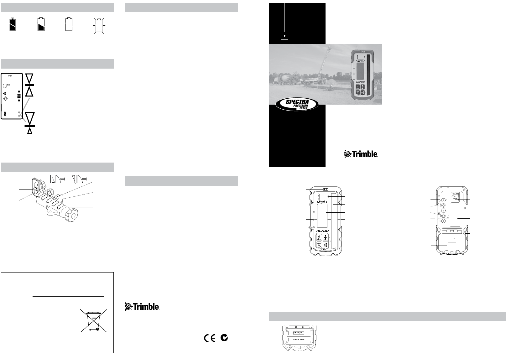
1. Keypad - Power, Accuracy, Units & Volume switches.
2. LED-Display - Green for on-grade & Red for high / low
3. Beeper output - Fast, solid & slow audible signal.
4. Bubble Vial - aids in keeping HR700 level.
5. Anti-strobe sensor - Reduces false indication from
strobe lights.
6. SuperCell Reception Window - 5 in / 127 mm of height.
7. Front LCD - Displays elevation, settings and status.
8. On-grade Mark - Aligned with laser center on-grade
reading.
9. Battery Door & Latch for two “AA” batteries.
10. Marking Notch (3.15 in / 80 mm from top).
11. Captive Screw Thread, Center on-grade clamp position.
12. Captive Screw Thread, Offset on-grade clamp position.
13. Clamp Guides - Dimples align rod clamp.
14. Serial Number / ID Label.
15. Rear LCD - repeats indications of front LCD.
16. Rubber over mold - Protects the unit from drops
4
6
7
5
1
2
3
8
9
10
11
12
14
15
16
13
Front view
Rear view
Working Radius: 1 m - 460 m (3 ft - 1500 ft)
(Laser dependent):
Laser Detection Height: 127 mm (5“)
Numeric Readout Height: 102 mm (4“)
Accuracy (Dead band):
Ultra Fine 0.5 mm 0.02 in 1/32 in
Super Fine 1.0 mm 0.05 in 1/16 in
Fine 2.0 mm 0.10 in 1/8 in
Medium 5.0 mm 0.20 in 1/4 in
Coarse 10.0 mm 0.50 in 1/2 in
Calibration 0.1 mm 0.01 in 1/64 in
Reception Angle: ± 45° minimum
Detectable Spectrum: 610 nm ... 780 nm
Beeper Volumes: Loud = 110 dBA
Medium = 95 dBA
Low = 65 dBA
LED Grade Indicators: Front, Green on-grade,
Red Hi/Low
Power Supply: 2 x 1.5 Volt “AA” batteries
Battery Life: 60+ hours
Automatic Shut Off: Selectable, 30 min, 24 h, Off
Environmental: Waterproof, Dustproof to IP67
Weight without clamp: 371 g (13.1 oz.)
Dimensions without
clamp: 168 x 76 x 36 mm
(6.6” x 3.0” x 1.4”)
Operating Temperature: -20°C...+60°C (-4°F... +140°F)
Storage Temperature: -40°C...+70°C (-40°F...+158°F)
*Specifications subject to change without notice.
Trimble warrants the HL700 to be free of defects in material and work-
manship for a period of three years. Trimble or its authorized service
center will repair or replace, at its option, any defective part, or the entire
product, for which notice has been given during the warranty period. If
required, travel and per diem expenses to and from the place where
repairs are made will be charged to the customer at the prevailing rates.
Customers should send the product to Trimble Navigation Ltd. or the
nearest authorized service center for warranty repairs or exchange,
freight prepaid. Any evidence of negligent, abnormal use, accident,
or any attempt to repair the product by other than factory-authorized
personnel using Trimble certied or recommended parts, automatically
voids the warranty. The foregoing states the entire liability of Trimble
regarding the purchase and use of its equipment. Trimble will not be
held responsible for any consequential loss or damage of any kind. This
warranty is in lieu of all other warranties, except as set forth above,
including any implied warranty merchantability of tness for a particular
purpose, are hereby disclaimed. This warranty is in lieu of all other
warranties, expressed or implied.
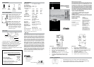
Battery Status
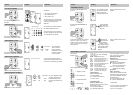
Rod Clamp
Move clamp position
Center on-grade clamp position - clamp
position is sensed automatically and
displayed. Standard center position displays
an equal amount of information above
and below grade. With no clamp, center
on-grade.
Offset on-grade clamp position - clamp
position is sensed automatically and
displayed. Offset clamp position moves
the on-grade location to allow more grade
information to be displayed above grade.
This is useful in applications where going
below grade is not required, i.e. driving
stakes down to grade.
Full -
Batteries OK
Half -
Initial
Warning
Outline -
Approx.
30 Minutes
Remaining
Flashing -
Change
Batteries
Notice to Our European Union Customers
For product recycling instructions and more information,
please go to: www.trimble.com/environment/summary.html
Recycling in Europe
To recycle Trimble WEEE,
call: +31 497 53 2430, and
ask for the “WEEE associate,” or
Mail a request for recycling instructions to:
Trimble Europe BV c/o Menlo Worldwide Logistics
Meerheide 45 5521 DZ Eersel, NL
1. Open the battery door using a coin or similar pry device to release the battery door tab.
2. Insert two AA batteries noting the plus (+) and minus (-) diagrams inside the battery housing.
3. Close the battery door. Push down until it “clicks” into the locked position.
Trimble Construction Division
5475 Kellenburger Road
Dayton, Ohio 45424-1099
U.S.A.
+1-937-245-5600 Phone
www.trimble.com
© 2008, Trimble Navigation Limited. All rights reserved.
Reorder PN 1277-3850 (05/08)
Specications
Warranty
Installing the Batteries
4
3
2
1
5
6
1. Captive Rod Clamp Screw - attaches to the back of detector.
2. Alignment Points (2) - help secure and align rod clamp.
3. Clamping Screw Knob - secures clamp to rods by moving the
traveling jaw. Clockwise tightens; Counterclockwise loosens.
4. Reference Bar - top of bar is aligned with on-grade.
5. Traveling Jaw - moving jaw grips tightly to rods.
6. Reversible Face - slanted face for round and oval rods; flat face
for rectangular and square rods.
N324