


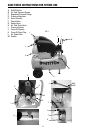
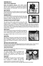
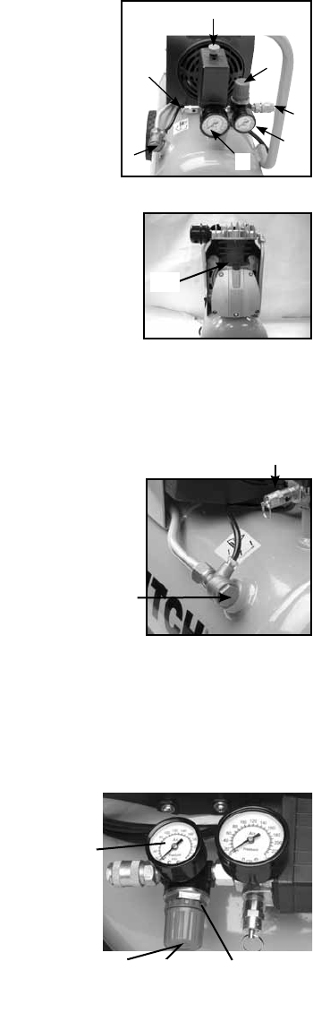
FEATURES (FIG. 1)
B
G
C
D
F
A
KNOW YOUR AIR COMPRESSOR
with your unit to familiarize yourself with the location of
various controls and adjustments. Save this manual for
future reference.
ON/OFF SWITCH
power to the pressure switch and OFF to remove power at
the end of each use.
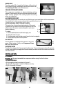
PRESSURE SWITCH
J
The Pressure Switch (I) automatically starts the motor when
the air tank pressure drops below the factory set cut-in
pressure. It stops the motor when the air tank pressure
reaches the factory set cut-out pressure.
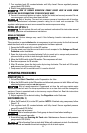
PRESSURE RELEASE VALVE (NOT SHOWN)
The pressure release valve located on the side of the
pressure switch, is designed to automatically release
compressed air from the compressor head and the outlet tube when the air compressor
reaches cut-out pressure or is shut off. The pressure release valve allows the motor to
restart freely. When the motor stops running, air will be heard escaping from this valve for
reaches cut-out pressure.
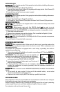
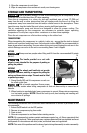
SAFETY VALVE
F
G
If the Pressure Switch (I) does not shut off the air compressor
at its cut-out pressure setting, the Safety Valve (G) will
protect against high pressure by popping out at its factory
set pressure (slightly higher than the pressure switch cut-
out setting).
CHECK VALVE
When the air compressor is operating, the check valve (F) is
open, allowing compressed air to enter the air tank. When
the air compressor reaches cut-out pressure, the check
valve closes, allowing air pressure to remain inside the air
tank.
UNIVERSAL QUICK CONNECT BODY
connections simple and easy.
TANK PRESSURE GAUGE
The tank pressure gauge (B) indicates the reserve air pressure in the tank.
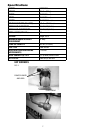
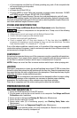
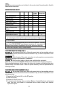
REGULATED PRESSURE GAUGE
D
C
Lock Collar
The outlet pressure gauge (C) indicates the
air pressure available at the outlet side of the
regulator. This pressure is controlled by the
regulator and is always less than or equal to the
tank pressure.
REGULATOR
The regulator (D) controls the air pressure shown
on the outlet pressure gauge. Turn regulator
knob clockwise to increase pressure and
counterclockwise to decrease pressure. When the
desired pressure is reached turn collar under knob against knob to lock in place.