Adjustment Procedures
THS710A, THS720A, THS730A & THS720P Service Manual
5–3
Accessing the Adjustment-Lockout Jumper
Before adjusting the instrument you must (temporarily) remove the internal
adjustment-lockout jumper. You will need a 12 in ⋅ lb (1.3 N ⋅ m) torque-limiting
screwdriver with Torx T-15 tip and a pair of needle-nose pliers to access and
remove the jumper.
WARNING. Before doing this or any other procedure in this manual, read the
General Safety Summary and Service Safety Summary found at the beginning of
this manual. Also, to prevent possible injury to service personnel or damage to
electrical components, read Preventing ESD on page 6–1.
Use this procedure to access and remove the adjustment-lockout jumper.
1. Disconnect all probes, cables, or meter leads from the instrument.
2. Disconnect the AC adapter, open the battery door, and remove the battery.
3. Place the TekScope instrument face down on a soft surface (such as an
anti-static mat).
4. Use the torque-limiting Torx T-15 screwdriver to remove the four screws
that hold the case together.
5. Holding the case together, pick it up and place it back side down on a soft
surface.
6. As you lift the front cover off the instrument, press the buttons as necessary
to prevent the switch mat from coming off with the front cover.
7. To remove the switch mat, lift it off the switch flex-circuit assembly. Place it
button-side down on a clean surface.
CAUTION. To avoid contamination of switch contacts, do not touch the carbon
contacts on the switch flex-circuit assembly or on the back side of the switch
mat.
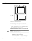
8. Fold the switch flex-circuit assembly toward you to expose the display
module, inverter board, and adjustment-lockout jumper. The jumper location
is shown in Figure 5–1.
9. Use the needle nose pliers to remove the adjustment-lockout jumper from the
instrument. Set the jumper aside for replacement after the adjustment is
complete.
10. To reassemble the instrument, fold the switch flex-circuit assembly back
over the display module and inverter board.


