Maintenance
VITS100 NTSC VITS Inserter Instruction Manual
7–11
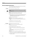
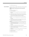
3. Remove the screw and hex nut that attach the power transistor to the outside
of the metal oven.
4. Remove the oven from the Inserter board by carefully pulling the oven off
the seven square pins that attach it to the Inserter board.
5. Remove the screw attaching the metal cover to the oven.
6. Remove the screw that holds the oscillator circuit board to the oven and then
pull the oscillator out of the oven.
Replacement. Use the following procedure to replace the oscillator circuit board
and oven assembly.
1. Set the oscillator circuit board in the oven. Install the screw that attaches the
circuit board to the oven.
2. Set the metal oven cover in place and install the attaching screw.
3. Carefully press the metal oven onto the seven square pins that connect it to
the Inserter board.
4. Reinstall the screw and hex nut that attach the power transistor to the outside
of the metal oven.
5. Set the plastic oven cover in place and install the two screws that attach the
oven case to the inserter circuit board.
6. Replace the instrument top cover.
Diagnostics
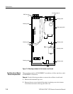
The primary means of troubleshooting this instrument is through built-in
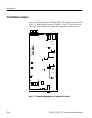
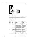
diagnostic routines that are accessed through rotary switch S8. (To locate S8, see
Figure 7–3.)
The built-in diagnostics are free-running, continuous loop routines during which
the processor sends a periodic signal through a particular data path.The signal
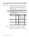
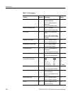
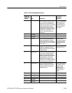
can then be viewed on a scope at points along the path to isolate problems. Table
7–3 lists the S8 settings that call the routines; it also provides a short description
of each routine.
Three of the routines—the RAM, ARCTAN, and CTC tests—run automatically
each time the instrument is powered up. If any of these fail, the front-panel
UNLOCKED LED lights, and the routine runs again. The VITS inserter will not
lock to program video until it successfully completes the power-up diagnostics.


