


iIS-010 series product specification
Ver. B (Oct. 12 200 )
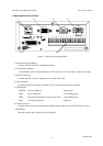
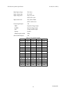
8. Parallel I/O
8 inputs and 7 outputs parallel I/O.
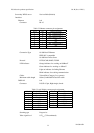
Table 1. Parallel I/O terminal functions
NAME I/O Function Name I/O Function
COM0
I
Common for inputs COM1
O
Common for outputs
GPI0
I
GPO0
O
Result (Pass) output
GPI1
I
GPO1
O
RESERVE
GPI2
I
GPO2
O
Result (Recycle) output
GPI3
I
Select solution input
(4bit, ID00~15)
GPO3
O
Result (Reject) output
SEL
I
Change solution input STR
O
Strobe pulse output
D.TRIG
I
Decision trigger input RDY
O
Ready signal output
TRIG
I
Inspection trigger input
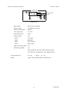
COM0: Common input for all other inputs.
GPI0 ~ 3: 4 inputs for solution selection. This is a BCD code representing 16 different solutions that
can be loaded.
SEL: 1 input for job change - This input will generate an interrupt to the CPU informing it that a
line changeover is taking place. The system will then load one of 16 predefined solutions
according to the BCD code present on the job selection inputs. During this process, the
ready signal will go OFF indicating a busy state.
D.TRIG: 1 decision trigger input representing detection of a valid part to make a decision on.
Decisions are queued following every inspection.
TRIG 1 inspection trigger input representing detection of a valid part to inspect.
COM1: Common output for all other outputs.
GPO0 ~ 3: 4 outputs for pass, fail, rework and reserve
STR: 1 strobe light control with offset and pulse width programmable.
RDY: 1 ready indicator. This OUTPUT will be active when the iIS system is available to process
parts. It is a level sensitive signal where a ON indicates the system is available and a OFF
indicates that it is busy, not configured or unable to continue due to a catastrophic event.
7
D4130145B