


Servicing the Fluid Section
Use the following procedures to service the valves and repack
the fluid section. Perform the following steps before
performing any maintenance on the fluid section.
1. Loosen and remove the four front cover screws. Remove
the front cover.
2. Position the crankshaft/slider assembly at the bottom,
dead-center of its stroke so that the connecting pin and
retaining ring are visible below the slider assembly. This
is done by turning the sprayer on and off in short bursts
until the connecting pin is visible below the slider housing.
3. Turn off and unplug the unit.
Before proceeding, follow the Pressure Relief Procedure
outlined previously in this manual. Additionally, follow all
other warnings to reduce the risk of an injection injury,
injury from moving parts or electric shock. Always unplug
the sprayer before servicing!
4. Remove the return hose from the clamp on the siphon
tube.
5. Unscrew the siphon tube/siphon set from the foot valve.
6. Loosen and remove the high-pressure hose from the
nipple on the back of the upper housing of the fluid
section.
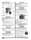
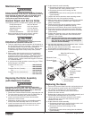
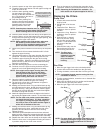
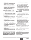
Servicing the Valves
The design of the fluid section
allows access to the foot valve and
seat as well as the outlet valve and
seat without completely
disassembling the fluid section. It
is possible that the valves may not
seat properly because of debris
stuck in the foot valve seat or outlet
valve seat. Use the following
instructions to clean the valves and
reverse or replace the seats.
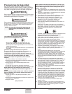
1. Loosen and remove the foot
valve housing from the lower
housing.
2. Clean out any debris in the foot
valve housing and examine the
housing and the foot valve
seat. If the seat is damaged,
reverse or replace the seat.
3. Using two wrenches, hold the
upper housing at the wrench
flats with one wrench and loosen the lower housing with
the other. Remove the lower housing.
4. Using a 3/4” wrench, loosen and
remove the outlet valve retainer
from the piston rod.
5. Clean out any debris and
examine the retainer and outlet
valve seat. If the seat is
damaged, reverse or replace the
seat.
6. Remove, clean, and inspect the
outlet valve cage and outlet valve
ball. Replace if they are worn or
damaged.
7. Reassemble the valves by reversing the steps above.
NOTE: Always service the
outlet valve with the
piston rod attached to
the pump. This will
prevent the piston rod
from rotating during
disassembly of the
outlet valve.
Outlet Valve
Retainer
Nylon
Washer
Outlet Valve
Seat
Outlet Valve
Ball
Outlet Valve
Cage
Outlet Valve
Seal
Piston Rod
Upper
Housing
Lower
Housing
Foot Valve
Housing
Black
O-Ring
O-ring
White
Back-Up
Ring
Foot Valve
Seat
Foot Valve
Ball
Foot Valve
Cage
Lower
Housing
Upper
Housing
WARNING
10 ©Titan Tool Inc. All rights reserved.
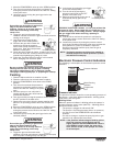
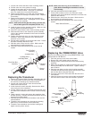
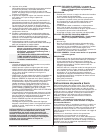
Repacking the Fluid Section
1. Remove the foot valve
assembly and the lower
housing using the steps in the
“Servicing the Valves”
procedure above.
2. Slide the retaining ring up on
the slider assembly to expose
the connecting pin.
3. Push the connecting pin back
through the slider assembly
and piston. The connecting
pin will fall into a recessed
area of the gear box housing
where it can be retrieved.
4. Tap the knock-off nut with a
soft hammer so that it turns
counterclockwise and loosens.
5. Turn the fluid section
counterclockwise to remove it
from the gear box housing.
6. Place the upper housing
upright in a vise by clamping
on the wrench flats.
7. Using a wrench, remove the
upper seal retainer.
8. Slide the piston rod out
through the bottom of the
upper housing.
9. Inspect the piston rod for wear
and replace if necessary.
10. Remove the upper and lower
packings from the upper housing.
11. Clean the upper housing. Inspect the upper housing for
damage and replace if necessary.
12. Locate the new upper and lower packings and remove the
pre-form tools. Save the upper packing pre-form tool for
use as the piston insertion tool later in this procedure.
13. Pack the areas between the
packing lips with grease.
Lubricate the o-rings on the
exterior of the packings with
grease.
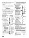
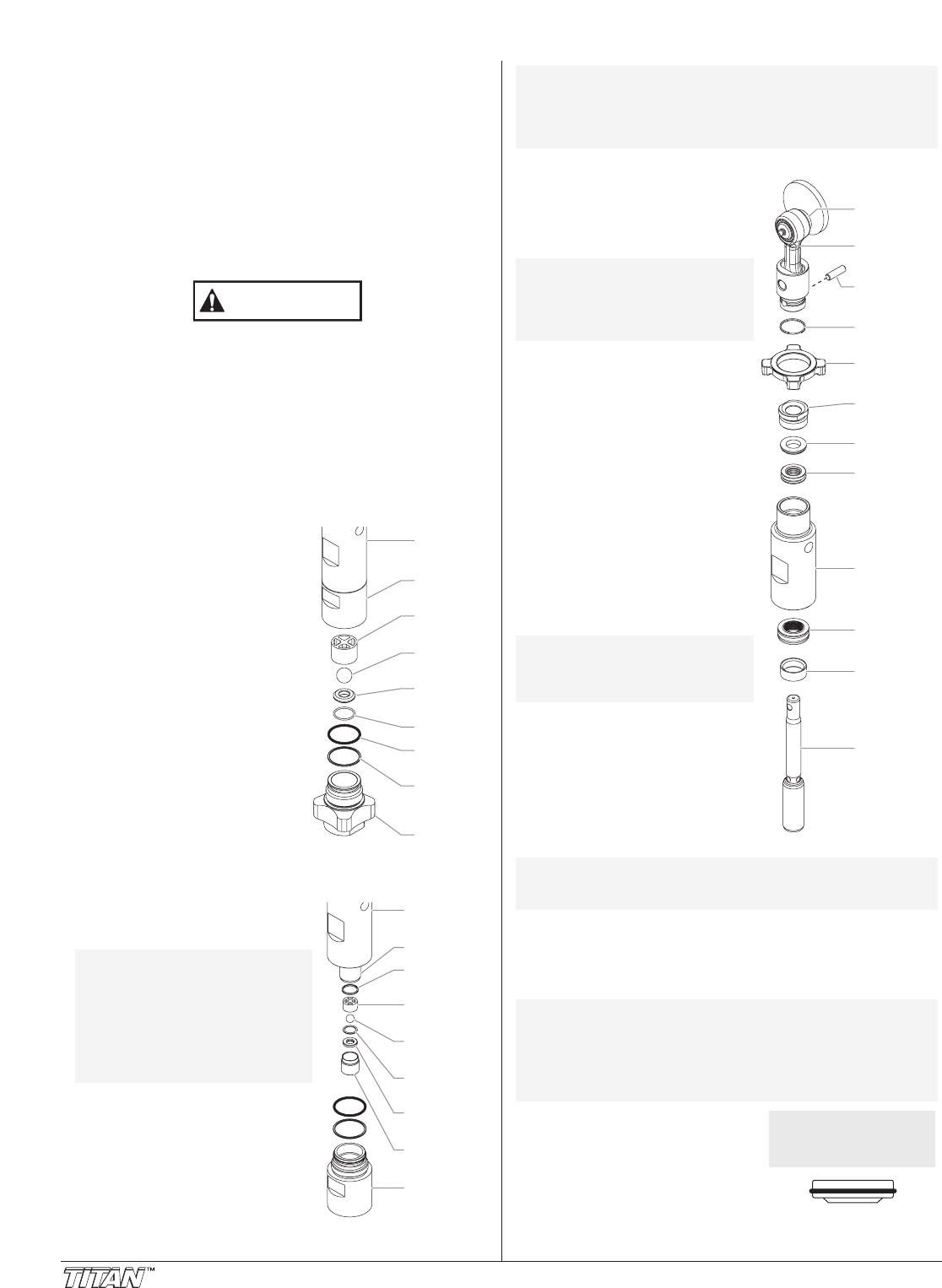
14. Insert the upper packing into the
top of the upper housing with
the raised lip on the packing
facing down.
Install upper packing
with raised lip
facing down.
Raised Lip
NOTE: The factory-installed packings are black in
color. The replacement packings in the packing
replacement kit are white.
Do not remove the pre-form tools from the
upper and lower packings until immediately
before they are installed into the upper housing.
NOTE: Be careful not to scratch, score, or otherwise
damage the upper housing during removal of
the packings.
NOTE: Do not over-tighten
the vise. Damage to
the upper housing
may occur.
NOTE: The outlet valve does
not need to be
disassembled from
the piston rod for this
procedure.
Retaining
Ring
Connecting
Pin
Slider
Assembly
Crankshaft
Knock-Off
Nut
Upper Seal
Retainer
Spacer
Upper
Packing
Lower
Packing
Upper
Housing
Piston Rod
Wear Ring
NOTE: During reassembly, make sure the black o-rings
and the white back-up rings between the upper
housing and lower housing as well as between
the lower housing and the foot valve housing
are lubricated with grease and in position.