


15. Insert the spacer on top of the upper packing.
16. Thread the upper seal retainer into the upper housing and
torque to 25-30 ft. lbs.
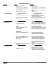
17. Insert the lower packing partially
into the bottom of the upper
housing so that the side that has
the o-ring closest to the face of
the packing faces up.
18. Push the lower packing into
position using the lower packing
insertion tool (see Fluid Section
Assembly parts list for lower
packing insertion tool P/N).
19. Place the piston insertion tool over the top of the piston rod.
20. Insert the piston rod into the bottom of the upper housing,
through the lower packing, through the upper packing, and
out through the upper seal retainer.
21. Remove the piston insertion tool from the top of the piston
rod.
22. Turn the knock-off nut counterclockwise until it is flush
against the upper housing.
23. Lubricate the threads on the upper housing with anti-seize
compound. Remove the upper housing from the vise.
24. Thread the upper housing into the gear box housing,
turning clockwise. When the connecting pin hole on the
piston rod lines up with the hole in the slider assembly,
insert the connecting pin.
25. Slide the retaining ring down over the connecting pin.
26. Continue to turn the upper housing clockwise until the
knock-off nut is flush against the gear box housing.
27. Once the nipple is positioned, turn the knock-off nut
clockwise until it contacts the gear box housing.
28. Tap the knock-off nut with a soft hammer to tighten it
against the gear box housing.
29. Making sure that the black o-ring and white back-up ring
are lubricated and in place, thread the lower housing into
the upper housing. Using two wrenches, hold the upper
housing at the wrench flats with one wrench and tighten
the lower housing with the other.
30. Attach the high-pressure hose to the nipple on the back of
the housing and tighten with a wrench. Do not kink the hose.
31. Making sure that the black o-ring and white back-up ring
are lubricated and in place, reassemble the foot valve
assembly and and thread it into the lower housing.
Tighten securely.
32. Thread the siphon tube/siphon set into the foot valve and
tighten securely. Make sure to wrap the threads on the down
tube/siphon hose adapter with Teflon tape before assembly.
33. Replace the return hose into the clamp on the siphon tube.
34. Place the front cover on the gearbox housing and secure
in position using the four front cover screws.
NOTE: For low rider units, make sure the hose does
not touch the cart frame. If it does, reposition
the nipple by turning the upper housing until
the hose is clear of the frame and the nipple is
within 45º of the back of the unit.
NOTE: If the nipple on the upper housing does not
face the back of the unit, turn the upper
housing counterclockwise until the nipple
faces the back of the unit. Do not turn the
upper housing more than one full turn.
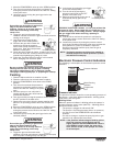
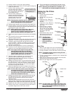
NOTE: When repacking the fluid section, make sure
the raised lip on the bottom of the lower
packing is fully outside the packing around the
piston rod after insertion of the piston rod.
NOTE: Coat the piston insertion tool (i.e., upper packing
pre-form tool) and the piston rod with grease
before inserting them into the pump block.
Install lower packing with
the side that has the o-ring
closest to the face of the
packing facing up.
Closer
Top
35. Turn on the sprayer by following the procedure in the
“Operation” section of this manual and check for leaks.
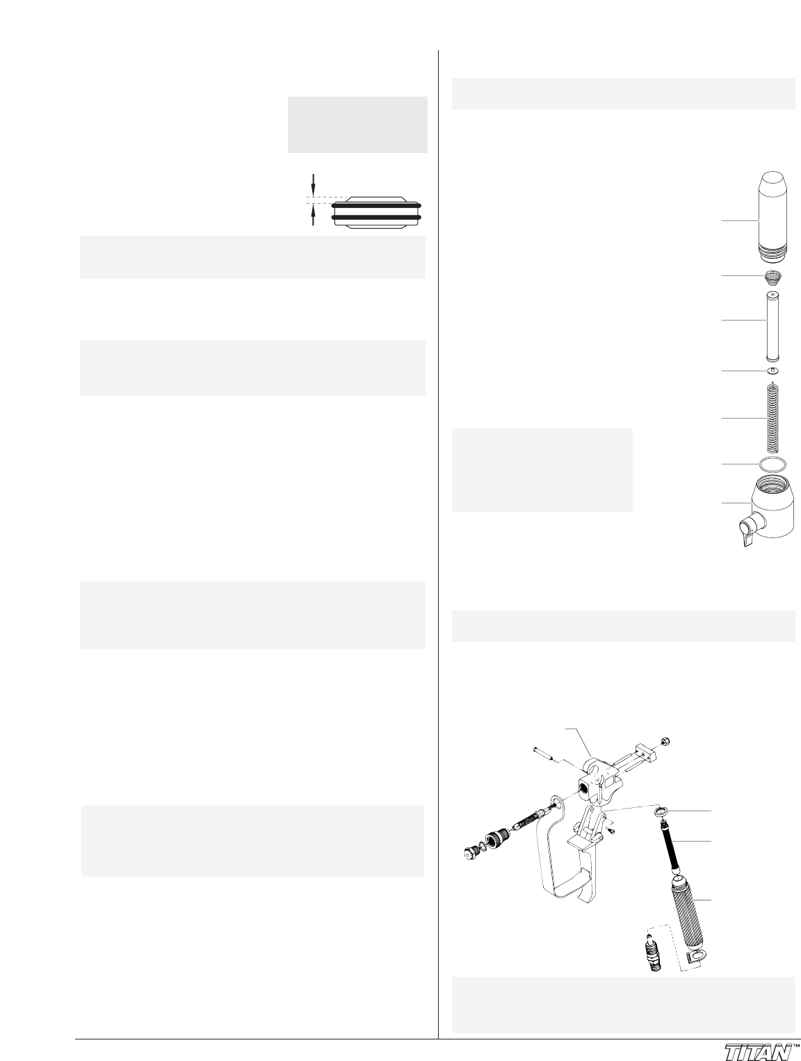
Replacing the Filters
Pump Filter
1. Loosen and remove the filter
body by hand.
2. Slip the filter off of the core
spring.
3. Inspect the filter. Based on
inspection, clean or replace
the filter.
4. Inspect the o-ring. Based on
inspection, clean or replace
the o-ring.
5. Slide the new or cleaned
filter over the core spring
with the filter spring adapter
in place. Push the filter into
the center of the filter
housing.
6. Slide the filter body over the
filter and thread it into the
filter housing until secure.
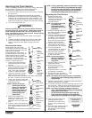
Gun Filter
1. Move the gun trigger lock to the unlocked position.
2. Loosen and remove the handle from the gun body.
3. Turning clockwise, unscrew the filter from the gun body.
4. Turning counterclockwise, screw the new or cleaned filter
into the gun body.
5. Make sure the handle seal is in position and thread the
handle into the gun body until secure.
6. Move the gun trigger lock to the locked position.
NOTE: For more detail, part number information, and
assembly drawings at larger scale, please see
the LX -80 Professional Airless Gun Owner's
Manual (#313-012).
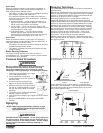
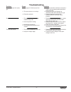
Gun Body
Handle Seal
Filter
Handle
NOTE: Left-handed threads require turning the filter
clockwise to remove.
NOTE: The filter body
should be hand-
tightened, but make
sure it is seated
fully into the filter
housing.
Filter Body
Filter Spring
Filter Spring
Adapter
Core Spring
Filter
O-ring
Filter Housing
NOTE: Repacking kit P/N 800-273 is available. For
best results use all parts supplied in this kit.
©Titan Tool Inc. All rights reserved. 11