


©Titan Tool Inc. All rights reserved. 19
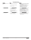
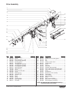
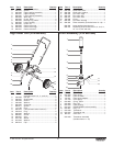
Item Part # Description Quantity
1 800-078 Electronic cover ..........................................1
2 800-205 Screw..........................................................3
3 800-224 Motor assembly, 1.1 HP .............................1
4 800-256 Front end bell assembly .............................1
5 800-525 Housing gasket...........................................1
6 800-541 Shroud gasket.............................................1
7 800-261 1st stage gear assembly.............................1
8 800-262 2nd stage gear asembly .............................1
9 800-259 Front gearbox assembly.............................1
10 800-510 Slider assembly ..........................................1
11 800-253 Slider housing.............................................1
12 700-283 Screw..........................................................4
13 800-265 Front cover with label .................................1
14 800-284 Screw..........................................................4
15 800-382 Retaining ring..............................................1
16 800-753 Connecting pin............................................1
17 800-206 Screw..........................................................2
18 800-376 Relay...........................................................1
19 704-229 Screw..........................................................1
20 800-389 Circuit breaker ............................................1
21 800-075 Mounting plate ............................................1
22 800-077 Grommet.....................................................1
Item
Part # Description Quantity
23 800-076 Screw..........................................................1
24 800-274 Potentiometer mounting plate.....................1
25 700-176 Nut ..............................................................1
26 700-175 Cap .............................................................1
27 700-159 Pressure control knob.................................1
28 800-277 Potentiometer .............................................1
29 800-203 Screw..........................................................1
30 704-281 Port plug .....................................................1
31 800-043 LED cover...................................................2
32 800-278 Indicator lights assembly ............................1
33 800-096 Power cord w/strain relief (high rider).........1
800-093 Power cord w/strain relief (low rider)..........1
34 700-287 Screw..........................................................3
35 763-551 Lock washer................................................3
36 800-223 Electronic control assembly........................1
37 800-215 Fan shroud..................................................1
38 800-294 Fan assembly .............................................1
39 800-435 Baffle assembly ..........................................1
40 800-283 Screw..........................................................4
41 800-254 Motor shroud w/labels ................................1
42 800-366 Wire cover, 7” (not shown) .........................1
43 800-368 Wire assembly (not shown) ........................1
NOTE: All electrical work should be performed by a
Titan authorized service center.
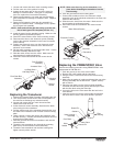
Drive Assembly
34
1
3
5
4
6
7
8
9
10
11
12
13
15
16
17
18
14
2
40
41
20
21
19
22
23
24
25
27
28
29
30
31
32
33
26
35
36
37
38
39