


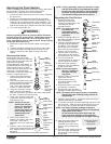
Maintenance
Before proceeding, follow the Pressure Relief Procedure
outlined previously in this manual. Additionally, follow all
other warnings to reduce the risk of an injection injury,
injury from moving parts or electric shock. Always
unplug the sprayer before servicing!
General Repair and Service Notes
The following tools are needed when repairing this sprayer:
Phillips Screwdriver 3/8" Hex Wrench
Needle Nose Pliers 5/16" Hex Wrench
Adjustable Wrench 1/4" Hex Wrench
Rubber Mallet 3/16" Hex Wrench
Flat-blade Screwdriver 5/32” Hex Wrench
1. Before repairing any part of the sprayer, read the
instructions carefully, including all warnings.
Never pull on a wire to disconnect it. Pulling on a wire
could loosen the connector from the wire.
2. Test your repair before regular operation of the sprayer to
be sure that the problem is corrected. If the sprayer does
not operate properly, review the repair procedure to
determine if everything was done correctly. Refer to the
Troubleshooting Charts to help identify other possible
problems.
3. Make certain that the service area is well ventilated in
case solvents are used during cleaning. Always wear
protective eyewear while servicing. Additional protective
equipment may be required depending on the type of
cleaning solvent. Always contact the supplier of solvents
for recommendations.
4. If you have any further questions concerning your TITAN
Airless Sprayer, call TITAN:
Customer Service (U.S.) .......................1-800-526-5362
Fax ................................................1-800-528-4826
Customer Service (Canada)..................1-800-565-8665
Fax ................................................ 1-905-856-8496
Customer Service (International)...........1-201-337-1240
Fax ................................................1-201-405-7449
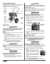
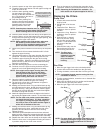
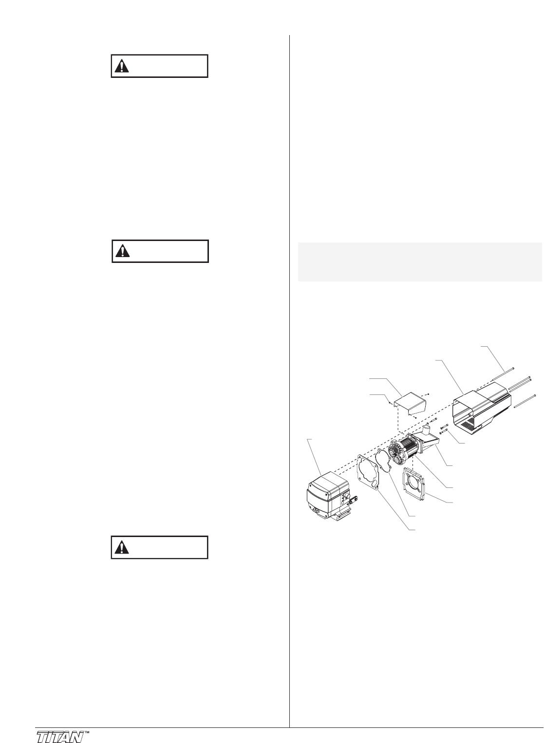
Replacing the Motor Assembly
(with Electronic Control)
Electrostatic discharge (ESD) potential could cause
damage to electronic control. Use Titan ESD wrist strap
P/N 700-1037 or equivalent when working on electronic
control with electronic cover removed.
1. Perform the Pressure Relief Procedure, and unplug the unit.
2. Turn the pressure control knob to the CLEAN position in
the red zone to discharge any stored electricity.
3. Loosen and remove the four motor shroud screws.
Remove the motor shroud.
4. Release the tie wrap on the top of the baffle assembly
and slip the baffle assembly down off of the motor.
5. Loosen and remove the three electronic cover screws.
Lift the electronic cover off of the electronic control
assembly on the motor.
WARNING
CAUTION
WARNING
8©Titan Tool Inc. All rights reserved.
6. At the electronic control assembly:
a. Disconnect the white wire coming from the power cord
and the white wire coming from the relay.
b. Disconnect the three wires coming from the
potentiometer.
c. Disconnect the seven wires coming from the indicator
lights assembly.
7. Loosen and remove the three motor mounting screws.
8. Pull the motor out of the gearbox housing.
9. With the motor removed, inspect the gears in the gearbox
housing for damage or excessive wear. Replace the
gears, if necessary.
10. Install the new motor into the gearbox housing. Make
sure the housing gasket is positioned properly.
11. Secure the motor with the three motor mounting screws.
12. Reconnect the wires to the electronic control assembly
(refer to the electrical schematic in the Parts List section
of this manual).
13. Position the electronic cover over the electronic control
assembly. Secure the electronic cover with the three
electronic cover screws.
14. Slip the baffle assembly up and around the motor. Secure
the baffle assembly with the tie wrap.
15. Slide the motor shroud over the motor. Make sure the
shroud gasket is positioned properly.
16. Secure the motor shroud with the four motor shroud
screws.
Replacing the Gears
1. Perform the Pressure Relief Procedure, and unplug the unit.
2. Turn the pressure control knob to the CLEAN position in
the red zone to discharge any stored electricity.
3. Loosen and remove the four motor shroud screws.
Remove the motor shroud.
4. Release the tie wrap on the top of the baffle assembly and
slip the baffle assembly down off of the motor.
5. Loosen and remove the three electronic cover screws.
Lift the electronic cover off of the electronic control
assembly on the motor.
6. At the electronic control assembly:
a. Disconnect the white wire coming from the power cord
and the white wire coming from the relay.
b. Disconnect the three wires coming from the
potentiometer.
c. Disconnect the seven wires coming from the indicator
lights assembly.
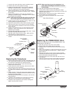
Electronic Cover
Motor Shroud
Motor Shroud Screws
Motor
Baffle Assembly
Housing Gasket
Shroud Gasket
Electronic Control
Assembly
Motor Mounting
Screw
Electronic Cover
Screw
Gearbox
Housing
NOTE: Use only Titan electronic cover screws to secure
the electronic cover (see Drive Assembly parts
list). Use of any other screws may damage the
electronic control assembly.