


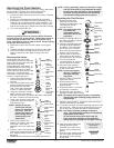
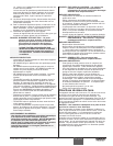
7. Loosen and remove the three motor mounting screws.
8. Pull the motor out of the gearbox housing.
9. Inspect the armature gear on the end of the motor for
damage or excessive wear. If this gear is completely
worn out, replace the front end bell assembly.
10. Remove and inspect the 1st stage gear and 2nd stage
gear assemblies for damage or excessive wear. Replace,
if necessary.
11.Remove and inspect the front gear box assembly for
damage or excessive wear. If damaged or worn, replace
the front gear box assembly.
12. Install the motor into the gearbox housing. Make sure the
housing gasket is positioned properly.
13. Secure the motor with the three motor mounting screws.
14. Reconnect the wires to the electronic control assembly
(refer to the electrical schematic in the Parts List section
of this manual).
15. Position the electronic cover over the electronic control
assembly. Secure the electronic cover with the three
electronic cover screws.
16. Slip the baffle assembly up and around the motor. Secure
the baffle assembly with the tie wrap.
17. Slide the motor shroud over the motor. Make sure the
shroud gasket is positioned properly.
18. Secure the motor shroud with the four motor shroud
screws.
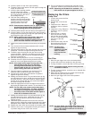
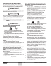
Replacing the Transducer
1. Perform the Pressure Relief Procedure, and unplug the unit.
2. Turn the pressure control knob to the CLEAN position in
the red zone to discharge any stored electricity.
3. Loosen and remove the four motor shroud screws.
Remove the motor shroud.
4. At the electronic control assembly, disconnect the black
wire coming from the transducer.
5. Pull the grommet out of the mounting plate and slide it up
the shaft of the transducer until it is clear of the mounting
plate.
6. Using a wrench, loosen and remove the transducer from
the filter housing. Carefully thread the transducer wire out
through the mounting plate.
7. Slide the grommet off of the old transducer and onto the
new transducer.
8. Thread the new transducer wire through the mounting
plate and up to the electronic control assembly.
9. Thread the new transducer into the filter housing and
tighten securely with a wrench.
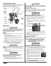
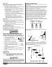
Front End Bell
Assembly
Armature Gear
1st Stage Gear
2nd Stage Gear
Front Gear Box
Assembly
Housing
Gasket
Shroud
Gasket
NOTE: Clean and refill the gear box cavity up to the rear
face of each gear with Lubriplate (P/N 314-171).
10. Push the grommet into the mounting plate.
11. Connect the transducer wire to the electronic control
assembly (refer to the electrical schematic in the Parts List
section of this manual).
12. Slide the motor shroud over the motor. Make sure the
shroud gasket is positioned properly.
13. Secure the motor shroud with the four motor shroud
screws.
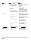
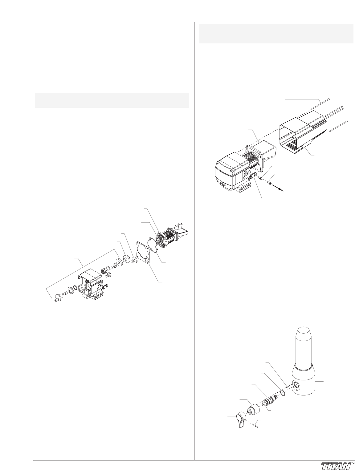
Replacing the PRIME/SPRAY Valve
Perform the following procedure using PRIME/SPRAY valve
replacement kit P/N 800-915.
1. Push the groove pin out of the valve handle.
2. Remove the valve handle and the cam base.
3. Using a wrench, loosen and remove the valve housing
assembly.
4. Make sure the gasket is in place and thread the new valve
housing assembly into the filter block. Tighten securely
with a wrench.
5. Place the cam base over the valve housing assembly.
Lubricate the cam base with grease and line up the cam
with the filter block using the dowel pin.
6. Line up the hole on the valve stem with the hole in the
valve handle.
7. Insert the groove pin into the valve handle and through
the valve stem to secure the valve handle in position.
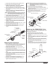
Gasket
Dowel Pin
Cam Base
Valve Stem
Filter
Housing
Valve Housing
Assembly
Valve
Handle
Groove Pin
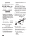
Motor Shroud
Transducer
Grommet
Motor Shroud Screws
Electronic Control
Assembly
Mounting Plate
To Filter
NOTE: Make sure the o-ring on the transducer is in
place before threading the transducer into the
filter housing.
©Titan Tool Inc. All rights reserved. 9