


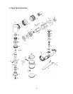
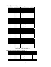
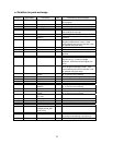

Parts no.
Figure no.
(ID number)
Part name Qty Guideline for parts exchange
38 150406 Tras bis (M4 x 6) 1
39 60736 Skirt band 1 When the deformed or damage is found.
40-1 110310 Screw (M3 x 10) (1)
40-2 2103 Nut (M3) (1)
41 Cap 1
42 60733 Skirt 1 When cut or cracked or worn-out.
43 130305 Screw (M3 x 5) 4
44 60735
φ30 x 4t pad
1 When surface flatness is lost
45 60738 Speed controller
(exclusive product)
1 When parts become worn such as the inlet
screws
60 60740 Housing 1
61 60741 Throttle Valve 1 When outer diameter is worn and air leaks
seriously from the valve pin sleeve joint
62 60742 Valve Plug 1
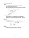
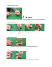
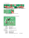
f. Assembly method
- Before assembly, clean each part and check for wear or damage. Use only proper
spare parts.
- Apply lubricant oil lightly on each part.
- Replace damaged O rings. Install O rings using grease (multipurpose grease - Military
Specifications G-46006, or equivalents).
- Assemble the parts carefully in reverse order from disassembly.
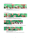
- Carefully confirm end clearance in the motor.
- Do not over-tighten the cup lock.
- When installing the angle housing, install the cap in the end of the angle housing
beforehand. Tighten the cup lock while confirming the position of the angle housing.
- Install the EX, shaft Assy., while confirming proper meshing of the gears. Never
assemble the gears to hit tooth to tooth.
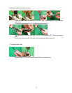
- After assembly, look for loose or missing screws.
- Apply lubricant oil into the air inlet, and run the tool at a medium pressure to make sure
it rotates freely.
Repair services after Warranty period & Parts supply contact
Tool Warehouse Inc.
Contact: Jeff Houk
3410 East 42
nd
Street,
Minneapolis, MN 55406-3333
Phone: 1-612-722-4260 Fax: 1-612-722-3415
e-mail:
sales@ToolWarehouseInc.com
3M Industrial Business Quality Direct / abrasives
Phone: 1-800-362-3550 (USA only)
3M Industrial Business Customer Response Center
900 Bush Avenue, Building 21-1W-10
St. Paul, MN 55106
Phone: 1-866-279-1235
www.3M.com/abrasives © 3M 2006
11