34 Operating Instructions
Constant Current Operation
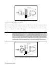
To set up the power supply for constant current operation:
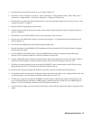
a. With power supply turned off, connect the load to the output terminals.
b. Turn on the power supply. Hold in DISPLAY OVP pushbutton switch and set OVP ADJUST potentiometer for the
desired OVP trip voltage. In CC mode the voltage setting will limit output voltage under quiescent conditions, and the
OVP circuit provides added protection against hardware faults.
c. Hold the DISPLAY SETTINGS pushbutton switch in, and rotate the VOLTAGE control to set desired voltage limit.
d. Adjust the output current to the desired level. The CC indicator should be on.
e. If a load change causes the voltage limit to be exceeded, the power supply automatically crosses over to constant
voltage operation and the output current drops proportionately. In setting the voltage limit, make adequate allowance
for voltage peaks that could cause unwanted mode crossover.
Remote Voltage Sensing
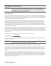
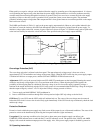
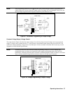
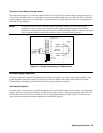
The remote sensing connections shown in Figure 3-6 improve the voltage regulation at the load by monitoring the voltage
there instead of at the supply’s output terminals. Remote sensing allows the power supply to automatically increase the
output voltage and compensate for the voltage drops in the load leads. This improves the voltage regulation at the load, and
is especially useful for CV operation with loads that vary and have significant load-lead resistance. Note that with remote
sensing, the internal voltmeter is connected at the load. Remote sensing has no effect during CC operation. When using
remote sensing, turn off the power supply before changing the rear-panel straps, sense leads, or load leads. Connect the unit
for remote voltage sensing by connecting load leads from + OUT and - OUT terminals to the load, disconnecting straps
between + Out and + S and between - Out and - S, and connecting sense leads from the + S and - S terminals to the load as
shown in Figure 3-6.
Note: Sensing is independent of other power supply functions; either local or remote sensing can be used
regardless of how the power supply is programmed.
The load leads should be of the heaviest practical wire gauge, at least heavy enough to limit the voltage drop in each load
lead to 0.5 volts. The power supply has been designed to minimize the effects of long load-lead inductance, but best results
will be obtained by using the shortest load leads practical.
Note: The OV circuit senses the voltage at + Out and at the output side of the internal current sampling resistor
in the – output lead. Remote voltage sensing compensates for a voltage drop of up to 0.5 V in each load
lead, and there may be up to 0.12 V drop between the – output and the internal sensing resistor at the
point the OVP circuit is connected. Therefore, the voltage sensed by the OVP circuit could be as much as
1.12 V more than the voltage being regulated at the load. It may be necessary to readjust the OVP trip
voltage to compensate for these drops when remote sensing.


