


Aiphone Communication Systems
1700 130th Ave. N.E.
Bellevue, WA 98005
(425) 455-0510
FAX (425) 455-0071
Toll Free Technical Support:
1-800-692-0200
E-mail tech@aiphone.com
LE-SS(R,GP) Instr.
0909BKJS
SPECIFICATIONS:
Power Source: Supplied by master station
Speaker: 20 ohms, 4W, 2.5" diameter, water proof and puncture resistant, 2.4 oz. magnet
Call Button: SPST call button. Call tone rings at master as long as button is held down. LED will remain lit for approx.
20 seconds (LEF, LEM-3, MP-3S, AP-5/10M only). Call tone only on LEM-1DL, LEM-1, and MP-1S.
LE-SS/-GP: Limited stop button. LE-SSR: Limited stop, red mushroom button
Communication: Hands free at sub. Master is push-to-talk,release-to-listen.
Faceplate: 12 gauge stainless steel
Mounting: Flush mount into a 2-gang box. Surface mount into SBX-2G, sold separately. Tamper proof screws
included (6x32 for use with flush gang box) with T-10 TORX bit.
Use hardware included with SBX-2G when installing sub into that unit.
Terminations: Color-coded prewired pigtails
Operating Temperature: Speaker rating: -67°F to 187°F
LE-SS(G) Switch rating: 14
F to 158°F; LE-SSR Switch Rating: -22 F to 185°F
Wiring: 2 conductors in a 1-master LEF, MP-S, or AP-M system. 3 conductors in a multi-master LEF system.
Shielded cable is recommended. Use Aiphone #822202 for LEM or MP-S. Use #822202 or
#822203 for LEF. Use #832202 for AP-M systems.
Wiring Distance: See system that unit is being used with for distance specifications.
Dimensions (H x W x D): LE-SS/-SSR/-GP alone: 4-11/16" x 4-11/16" x 2"
With SBX-2G(-GP2): 4-3/4" x 4-7/8" x 3-5/8" (Top) 2-3/8" (Bottom)
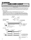
WIRING DIAGRAMS:
1
E
2
E
~
10
E
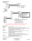
AP-M Master
Modifying LE-SS/-SSR/-GP
to work with AP-M Master:
1. Cut Brown wire on CP038.
(Brown wire jumpers J8 to J10.)
2. Tie Brown wire from J8 to
Orange wire on J9.
3. Tie Brown wire from J10 to
Yellow wire on J11.
Tie Blk and Grn wires together for all
installations with the MP-S and AP-M
systems.
Red
Blk
Grn
Brn
Org
Brn
Yel
Red
Blk
Grn
Brn
Org
Brn
Yel
LE-SS/LE-SSR
1
(2)
(3)
E
+
-
MP-S Master
+
-
PS-1225UL
MP-S SYSTEM:
AP-M SYSTEM:
WIRE DEFINITIONS:
Red: Hot side of speaker & call switch, connect to # of master
Black: Common communication, connect to E of master
Green: Negative side of call switch
Brown: Call switch, left intact for LEM, LEF.
Jumpered with Org/Yel for AP-M
Orange: Additional resistor circuit for AP-M
Yellow: Additional resistor circuit for AP-M
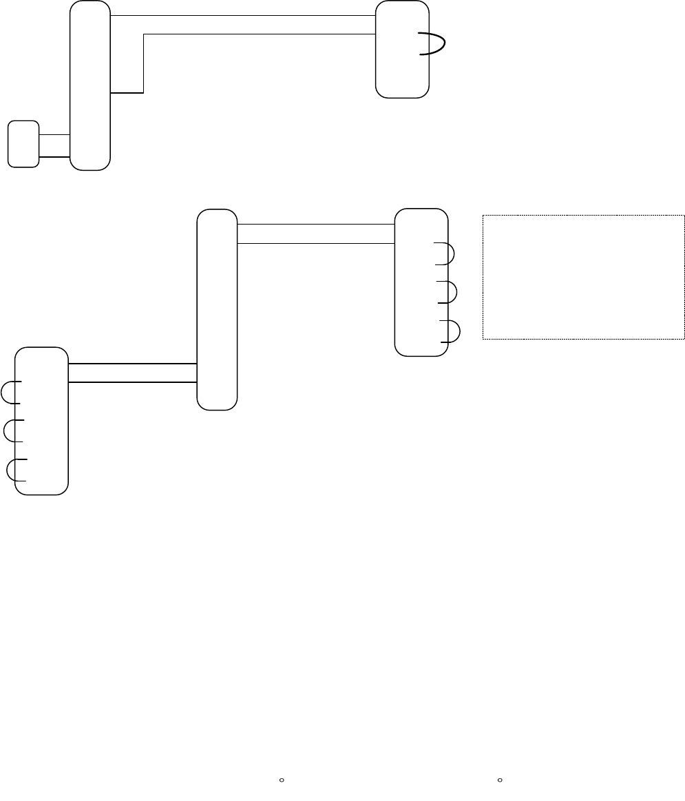
LE-SS(R,-GP) Sub
Red
Blk*
Grn
LE-SS(R,-GP) Sub
Jumper Green & Black
wires together.
Leave brown, orange,
and yellow wires
disconnected.
Intercom wiring must be run at least 20" away from any AC wiring, fluorescent lighting,
dimmer switches, or any other electronic device that may cause interference.