


bdiGDB
for GNU Debugger, BDI2000 (ARM11/Cortex-A8) User Manual 12
© Copyright 1997-2007 by ABATRON AG Switzerland V 1.04
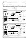
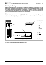
2.2.2 Power Supply from Target System
The BDI2000 needs to be supplied with 5 Volts (max. 1A) via BDI MAIN target connector (Rev. A) or
via TARGET A connector (Rev. B/C). This mode can only be used when the target system runs with
5V and the pin «Vcc Target» is able to deliver a current up to 1A@5V. For pin description and layout
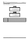
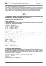
see chapter 2.1 «Connecting the BDI2000 to Target». Insert the enclosed Jumper as shown in figure
below. Please ensure that the jumper is inserted correctly.
For error-free operation, the power supply to the BDI2000 must be between 4.75V and 5.25V DC.
The maximal tolerable supply voltage is 5.25 VDC. Any higher voltage or a wrong polarity
might destroy the electronics.
!
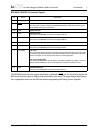
BDI TRGT MODE BDI MAIN BDI OPTION
13
1
14
2
BDI OPTION
Connector
The green LEDs «BDI» and «TRGT» marked light up when target is powered up
Jumper
and the jumper is inserted correctly
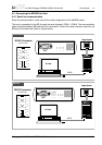
1 - NOT USED
2 - GROUND
3 - NOT USED
4 - GROUND
5 - NOT USED
6 - GROUND
7 - NOT USED
8 - GROUND
9 - NOT USED
10 - GROUND
11 - NOT USED
12 - Vcc (+5V)
13 - Vcc Target (+5V)
14 - Vcc BDI2000 (+5V)
Rev. A
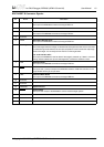
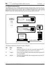
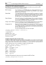
BDI TRGT MODE TARGET A TARGET B
POWER
1 - Vcc BDI2000 (+5V)
2 - Vcc Target (+5V)
3 - GROUND
4 - NOT USED
Connector
RS232 POWER LI TX RX 10 BASE-T
1
2
3
4
The green LEDs «BDI» and «TRGT» marked light up when target is powered up
and the jumper is inserted correctly
Jumper
Rev. B/C