


Continuous-Time Ratiometric
Linear Hall Effect Sensors
A1301 and
A1302
7
Allegro MicroSystems, Inc.
115 Northeast Cutoff, Box 15036
Worcester, Massachusetts 01615-0036 (508) 853-5000
www.allegromicro.com
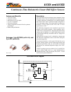
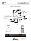
Package LH, 3-Pin; (SOT-23W)
0.15
0.00
.006
.000
1.17
0.75
.046
.030
0.50
0.30
.020
.012
2.10
1.85
.083
.073
3.00
2.70
.118
.106
1.49
NOM
.059
0.96
NOM
.038
0.20
0.08
.008
.003
8º
0º
0.60
0.25
.024
.010
C
SEATING
PLANE
A
B
3X
0.20 [.008] M C A B
0.15 [.006] M C A B
C0.10 [.004]
3X
0.95 .037
1.90 .075
0.25 .010
3.04
2.80
.120
.110
21
3
GAUGE PLANE
SEATING PLANE
B
A
B
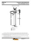
Preliminary dimensions, for reference only
Dimensions in millimeters
U.S. Customary dimensions (in.) in brackets, for reference only
(reference JEDEC TO-236 AB, except case width and terminal tip-to-tip)
Dimensions exclusive of mold flash, gate burrs, and dambar protrusions
Exact case and lead configuration at supplier discretion within limits shown
Hall element (not to scale)
Active Area Depth 0.28 [.011]
A
A
A
Terminal List
Symbol
Number
Description
Package LH Package UA
VCC 1 1 Connects power supply to chip
VOUT 2 3 Output from circuit
GND 3 2 Ground
Package LH
Package UA
Pin-out Drawings
231
21
3