


6
2.1.4 More about noise: Expanders and Noise-Gates
A lot of instruments such as microphones, amplifiers, guitar pickups, etc generate some noise, either at low frequ-
encies (hum) or at high frequencies (hiss) such noise will inevitably interfere with the quality of your audio signal.
Now, if you scream into a microphone you will not hear the noise generated by such microphone because such
noise will be "masked" by the higher level of the signal, your voice in this case.
But if you sing into your microphone more gently in a soft passage, the level of the signal generated by your voice
will get much closer to the floor noise level and such floor noise will become disturbing. In order to kill this problem
Expanders and noise-gates are used. An expander is the opposite of a compressor: attenuating the signal when
the amplitude drops they can limit the floor noise.
Now, we do not need dramatic expansion of a signal across the range, This would generate a resulting dynamic
range of over 150dB. For this reason the amplitude control will be applied only to those audio signals which are
below a set threshold. Those audio signals above the set threshold will not be affected. Noise-gate can be regarded
as a simple Expander. But the Expander will attenuate the audio signal continuously below the set threshold while
the noise-gate will simply dramatically cut-off the audio signal completely.
2.2 Voltage Controlled Amplifier (VCA)
The VCA is the soul of the CLE 2.0 and it is one of the best components available today in his category thanks to its
excellent performances in terms of distortion, linearity, noise and temperature stability.
2.3 Inputs
2.3.1 Take it easy: Balanced Inputs
To make your life easy and clean we have provided CLE 2.0 with electronically balanced inputs. Even if
you operate at high signal levels, hum and noise will be reduce automatically. There is also a servo-function
that will automatically adjust the internal level when unbalanced connectors are detected. The correction
if of 6dB and it will avoid differences in level in between input and output signal.
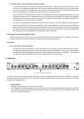
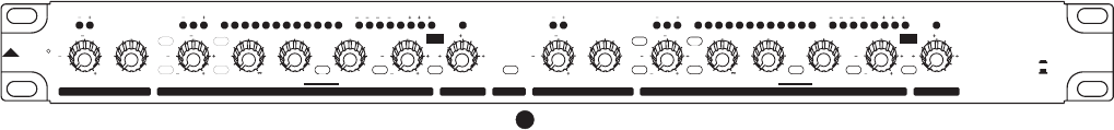
3. CONTROLS
Pic. 1 Front anel of he CLE 2.0PT
Your CLE 2.0 presents with right and left channels. Each channel is equipped with the same control elements: 7 push-button
switches, 8 rotary controls and 26 LEDs. You can easily operate the stereo made via pressing the Couple switch. The details
please refer to following content.
1. Couple Switch
Pressing this push-button for stereo mode operation.
When engaged, the Master channel (channel 1) will take control of both channels and override all the controls
and switches of channel 2 with the exception of the SC Monitor, SC External, SC Filter and Bypass switches as
well as the Peak Limiter control.
3
1
GAIN REDUCTION(dB) INPUT / OUTPUT LEVEL(dB)
THRESHOLD
THRESHOLD
dB/mSec
COUPLE
LIMITER
dB dBu
dBu
1:N
dBu
SC MONITOR
SMART
SC EXTERNAL
dB/Sec
N:1
I/O METER
EXPANDER / GATE
THRESHOLD
RATIO
COMPRESSOR
THRESHOLD
RATIO
ATTA CK
RELEASE OUTPUT GAIN
CH1
LIMITER
dB dBudBu 1:N dBu
SC MONITOR
SMART
SC EXTERNAL
dB/Sec
N:1
I/O METER
EXPANDER / GATE
THRESHOLD
RATIO
COMPRESSOR
THRESHOLD
RATIO
ATTA CK
RELEASE OUTPUT GAIN
CH2
THRESHOLD
THRESHOLD GAIN REDUCTION(dB) INPUT / OUTPUT LEVEL(dB)
POWER
ON
OFF
R
LTO
dB/mSec
SC FILTER
SC FILTER
0
0.05
5
12
0.3
10
10
0
20
20
OFF
60
35
15
OFF
8
7
2.5
1.5
1.2
30
20
40
10
10
2
4
1
6110
70
30
15
1
150
0.1 3
1.5
0.5
0
0
0.05
5
12
0.3
10
10
0
20
20
OFF
60
35
15
OFF
8
7
2.5
1.5
1.2
30
20
40
10
10
2
4
6
1
6110
70
30
15
1
150
0.1 3
1.5
0.5
0
DUAL MONO
CH 1 MASTER
0
30 27 24 21 18 15 12 9 6 4 2 1
12 0 LIM1261824
6
18
0
30 27 24 21 18 15 12 9 6 4 2 1
12 0 LIM1261824
6
18
10
184 18
4
10