


User’s Guide # L010167
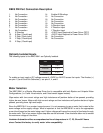
Microstep Selection (SW1 Settings)
Switches 2, 3 and 4, of the DIP switch select the number of microsteps per step. Table 7 shows the
standard resolution values along with the associated positions for the select switches. The standard wave-
forms are sinusoidal.
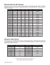
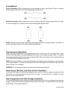
Setting the Output Current
The output current on the MBC10641 is set by an onboard potentiometer. This potentiometer determines
the per phase peak output current of the driver. The relationship between the output current and the
potentiometer value is as follows:
Table 7: Potentiometer values with respect to the output current
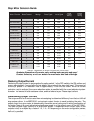
Refer to Table 5 for specific motor current settings.
Table 6: Microstep Selection on Switch 1.
noituloseR veR/spetS 1tceleS 2tceleS 3tceleS 4tceleS tnerruCecudeRotuA
1
002FFONONONOdelbasiD
2
004FFONONOFFOdelbasiD
5
0001FFONOFFONOdelbasiD
8
0061FFONOFFOFFOdelbasiD
01
0002FFOFFONONOdelbasiD
61
0023FFOFFONOFFOdelbasiD
23
0046FFOFFOFFONOdelbasiD
46
00821FFOFFOFFOFFOdelbasiD
1
002NONONONOdelbanE
2
004NONONOFFOdelbanE
5
0001NONOFFONOdelbanE
8
0061NONOFFOFFOdelbanE
01
0002NOFFONONOdelbanE
61
0023NOFFONOFFOdelbanE
23
0046NOFFOFFONOdelbanE
46
00821NOFFOFFOFFOdelbanE
tnerruCkaeP gnitteSretemoitnetoP tnerruCkaeP gnitteSretemoitnetoP
A5.1%0 A0.7%06
A3.2%01 A9.7%07
A1.3%02 A7.8%08
A0.4%03 A6.9%09
A0.5%04 A01%001
A0.6%05 ----