1
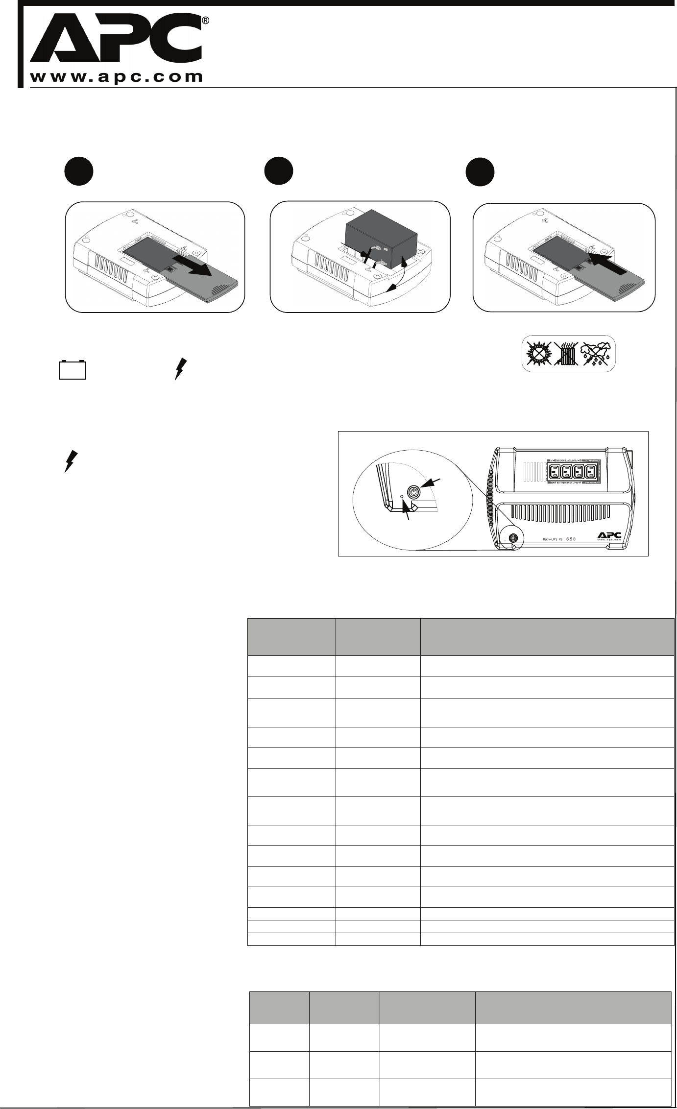
Connect Battery
For safety, the Back-UPS is shipped with one battery wire disconnected. The Back-UPS will not operate until the wire is connected to the touch safe battery
terminal.
NOTE: Small sparks may occur during battery connection. This is normal.
TURN the Back-UPS over, and slide
the battery compartment cover off of
the battery housing.
1
2
3
REMOVE the battery from the battery
compartment, and connect the black wire
to the negative (-) battery terminal. Ensure
the battery is installed as shown below.
INSTALL the battery compartment cover
back onto the battery housing.
Place the Back-UPS to avoid:
- Direct sunlight
- Excessive heat
- Excessive humidity or contact with fluids
Plug the Back-UPS power cord directly into a wall outlet, and not to a surge
protector or power strip. The wall outlet should be located near the equipment, and
easily accessible.
Power On
Power
Switch
UPS Status Indicator
(Green - OK, Red or Amber-
See User Manual)
Power O n
2
Surge Protection Only
These outlets provide full-time protection from surges even if the
Back-UPS is switched OFF. Plug your printer, fax machine,
scanner, or other peripherals that do not need battery power into
these outlets.
Battery Backup Surge Protection
These outlets are powered whenever the Back-UPS is switched
ON. During a power outage, or other utility problems (brownouts,
over-voltages), these outlets will be powered for a limited time by
the Back-UPS. Plug your computer, monitor, and two other data-
sensitive devices (external disk or tape drive) into these outlets.
3
990-2994B Copyright 2007 American Power Conversion Corp.
All other trademarks are property of their respective owners.
APC, Back-UPS and PowerChute are registered trademarks of American Power Conversion Corp.
Power On
Press the ON/OFF switch to power the unit
ON.
A single short beep, and the green “Power On”
indicator confirms that the Back-UPS is on and
ready to provide protection.
The Back-UPS should charge for at least 24
hours to ensure sufficient runtime. The unit is
being charged whenever it is connected to utility
power, whether the unit is turned ON or OFF.
The Back-UPS ES indicates its operating status using a combination of visual and audible indicators. Use the
following table to identify the status of the Back-UPS ES.
Visual Indications
(Power On - Green)
(Replace Battery - Red)
Audible Indication
(Buzzer)
Condition
GREEN On Off Power On - Back-UPS is supplying conditioned utility power to the
connected equipment.
GREEN On (Off during
4 beeps)
4 beeps repeated
every 30 seconds
On-Battery - Back-UPS is supplying battery power to the load
connected to the Battery outlets.
Flashing GREEN Constant Beeping
(every 1/2 second)
Low Battery Warning - The Back-UPS is supplying battery power to the
load connected to the battery outlets, and the battery has 1.5 minutes of
battery power remaining.
Alternating
GREEN & RED
Constant tone Bad Battery Detected - Battery needs to be charged, or is at end of life
and must be replaced (see Replace Battery).
Flashing
RED
Constant tone Battery Disconnected - The battery is disconnected or it is a bad
battery (see Replace Battery).
Off Short beep every
4 seconds
Low Battery Shutdown - During On Battery operation the battery
power was almost completely exhausted, and the Back-UPS is waiting
for utility power to return to normal.
Off Constant Tone On Battery Overload - Connected equipment requires more power
than provided by Back-UPS battery. Unplug devices one at a time to
remove overload. If not corrected contact APC Technical Support.
GREEN On Constant Tone On Line Overload - The power drawn by the connected equipment
exceeds the power capacity of the Battery Backup.
Flashing
RED
Chirp every 2 seconds Charger Warning - Back-UPS has experienced an internal problem, but
continues to power the load. Contact APC Technical Support.
Off Constant Tone Charger Fault - Back-UPS has an internal problem, and is no longer
powering the load. Contact APC Technical Support.
Alternating
GREEN/AMBER/RED
Off Button Program Mode - see Section 4, and the table below.
GREEN Flashing Off Low Sensitivity Mode - see Section 4, and the table below.
RED Flashing Off Medium Sensitivity Mode - see Section 4, and the table below.
AMBER Flashing Off High Sensitivity Mode - see Section 4, and the table below.
Status Indicators
4
Transfer Voltage and
Sensitivity Adjustment
(Optional)
In situations where the Back-UPS, or connected
equipment, appears too sensitive to the input volt-
age, it may be necessary to adjust the transfer
voltage. This is a very simple task that requires
the use of an ON/OFF push button. To adjust the
transfer voltage, perform the following steps:
1. Plug the Back-UPS into the utility power
source. The Back-UPS will be in “Standby
mode” (no indicators are lit).
2. Press the ON/OFF push button fully in for 10
seconds. The Online LED will begin glowing in
a cyclical order: GREEN-AMBER-RED, indi-
cating it is going into “Program mode”.
3. The Back-UPS will then indicate the current
sensitivity, as shown in the Transfer Voltage
and Sensitivity Adjustment table below.
4. To select the LOW sensitivity setting, press the
ON/OFF push button until the LED begins
flashing GREEN.
5. To select the MEDIUM sensitivity setting,
press the ON/OFF push button until the LED
begins flashing RED.
6. To select the HIGH sensitivity setting, press
the ON/OFF push button until the LED begins
flashing AMBER.
7. To exit Programming mode, once sensitivity is
set, wait approximately 5 seconds, and all of
the LED indicators will be off (unlit).
Connect Equipment
Trans
er Voltage and
ensitivity Adjustment
Indicators
Flashing
Sensitivity
Setting
Input Voltage Range
(For Utility Operation)
When to Use
Green
Flashing
LOW 155 - 290 Input voltage is extremely low or high.
Not recommended for computer loads.
Red Flashing MEDIUM
(factory default)
160 -280 Back-UPS frequently goes on battery.
Amber
Flashing
HIGH 165 - 270 Connected equipment is sensitive to voltage
fluctuations.
Connect AC Line Cord
Plug the Back-UPS power cord into a wall outlet, not a surge
protector or power strip. The outlet should be near the equipment
and easily accessible.
Back-UPS
®
BR650CI / BR650CI-AS
User Guide


