


2
When used properly, the STOP/GO LITE will indicate whether clamp connections will be correct. Connect the positive (red) clamp to the positive (POS, P, +) battery post. Touch the contact button of the
negative (black) clamp to the other battery post. Observe the L.E.D. lights in the STOP/GO LITE:
GREEN LIGHT: The first connection is correct. Make the second clamp connection per instructions.
RED LIGHT:
The first connection made with the positive clamp to the battery is incorrect. Attach the positive clamp to the other battery post and retest.
RED AND GREEN LIGHT: The battery charger is turned on. Turn the charger "OFF" and retest.
NO LIGHT:
Check for a shorted or open battery. Clean any corrosion from the clamp jaws and the battery post and retest. If still no light, use a voltmeter or other means to make certain you have
properly identified the polarity of the battery post. Then attach the clamps per instructions, disregarding the STOP/GO LITE.
18.
FOLLOW THESE STEPS WHEN THE BATTERY IS INSTALLED IN A VEHICLE. A SPARK NEAR THE BATTERY
MAY CAUSE A BATTERY EXPLOSION. TO REDUCE THE RISK OF A SPARK NEAR THE BATTERY:
a. Read the section "STOP/GO LITE INSTRUCTIONS" before proceeding.
b. Position the AC and DC cords to reduce the risk of damage by the hood, door, or moving engine parts.
c. Stay clear of fan blades, belts, pulleys, and other parts that can cause injury to persons.
d. Check the polarity of the battery post. The POSITIVE (POS, P, +) battery post usually has a larger diameter than the NEGATIVE (NEG, N, -) post.
e.
Determine which post of the battery is grounded (connected) to the chassis. If the negative post is grounded to the chassis (as in most vehicles), see item "f". If the positive post is grounded to the
chassis, see item "g".
f.
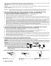
For negative-grounded vehicles, connect the POSITIVE (RED) clamp from the battery charger to the POSITIVE (POS, P, +) ungrounded post of the battery. Touch the contact button of the STOP/GO
LITE to the NEGATIVE (NEG, N, -) battery post. Interpret the light and take appropriate action. When the green light is on, connect the NEGATIVE (BLACK) clamp to the vehicle chassis, heavy gauge
metal part of the frame, or engine block, away from the battery. Do not connect to the carburetor, fuel lines, or sheet metal body parts.
g.
For positive-grounded vehicles, connect the POSITIVE (RED) clamp from the battery charger to the POSITIVE (POS, P, +) battery post. Touch the contact button of the STOP/GO LITE to the
NEGATIVE (NEG, N, -) battery post. Interpret the light and take appropriate action. When the green light is on, disconnect the POSITIVE (RED) clamp from the battery. Attach the NEGATIVE
(BLACK) clamp to the NEGATIVE (NEG, N, -) ungrounded post of the battery. Attach the POSITIVE (RED) clamp to the vehicle chassis or engine away from the battery. Do not connect the clamp to the
carburetor, fuel lines, or sheet-metal body parts. Connect to a heavy gauge metal part of the frame or engine block.
h.
When disconnecting the charger, turn the switches to OFF, disconnect the AC cord, remove the clamp from the vehicle chassis, and then remove the clamp from the battery terminal.
i. See the operating instructions for length of charge information.
19. FOLLOW THESE STEPS WHEN THE BATTERY IS OUTSIDE THE VEHICLE. A SPARK NEAR THE BATTERY MAY
CAUSE BATTERY EXPLOSION. TO REDUCE THE RISK OF A SPARK NEAR THE BATTERY:
a. Read section "STOP/GO LITE INSTRUCTIONS" before proceeding.
b. Check the polarity of the battery post. The POSITIVE (POS, P, +) usually has a larger diameter than the NEGATIVE (NEG, N, -) post.
c. Attach at least a 24 inch long 6-gauge (AWG) insulated battery cable to the NEGATIVE (NEG, N, -) battery post.
d. Connect the POSITIVE (RED) charger clamp to the POSITIVE (POS, P, +) post of the battery.
e.
Touch the contact button of the STOP/GO LITE to the free end of the battery cable. If the red light comes on, reverse the connections to the battery and retest. When the green light come on, position
yourself and the free end of the cable as far away from the battery as possible, then connect the NEGATIVE (BLACK) charger clamp to the free end of cable.
f. Do not face the battery when making the final connection.
g.
When disconnecting the charger, always do so in reverse sequence of connecting procedure, and break the first connection while standing as far away from the battery as practical.
h. A marine (boat) battery must be removed and charged on shore. To charge it on board requires equipment specially designed for marine use.
20.
GROUNDING AND AC POWER CORD CONNECTION INSTRUCTIONS
The charger should be grounded to reduce the risk of electric shock. This charger is equipped with an electric cord having an equipment grounding conductor and a grounding plug. The plug must be
plugged into an outlet that is properly installed and grounded in accordance with all local codes and ordinances.
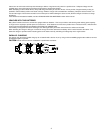
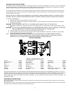
DANGER.
Never alter the AC cord or plug provided - if it will not fit the outlet, have a proper outlet installed by a qualified electrician. Improper connection can result in a risk of an electric shock. This
battery charger is for use on a nominal 120-volt circuit, and has a grounding plug that looks like the plug illustrated in FIGURE (A). A temporary adapter, which looks like the adapter illustrated in FIGURE (C),
may be used to connect this plug to a two-pole receptacle, as shown in FIGURE (B), until a properly grounded outlet can be installed by a qualified electrician.
DANGER. Before using an adapter as illustrated, be certain that the center screw of
the outlet plate is grounded. The green-colored rigid ear or lug extending from the adapter
must be connected to a properly grounded outlet - make certain it is grounded. If necessary,
replace the original outlet cover plate screw with a longer screw that will secure the adapter
ear or lug to the outlet cover plate and make ground connection to grounded outlet.
NOTE: USE OF AN ADAPTER IS NOT ALLOWED IN CANADA. IF A
GROUNDING TYPE RECEPTACLE IS NOT AVAILABLE, DO NOT USE
THIS APPLIANCE UNTIL THE PROPER OUTLET IS INSTALLED BY A
QUALIFIED ELECTRICIAN.
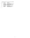
21.
NOTE: SIDE TERMINAL TO BE USED IN POSITIVE CLAMP ONLY!
For instructions for NEGATIVE clamp attachment refer to section 18 f or 18 g.
Storage position
Will not get lost. Always ready to use.
Extended position
Note: Pressure, when handle is squeezed, holds adapter firm.
Will not slip back.
Thrust on terminal
Note: Clamp is released and spring tension holds adapter
firm.
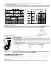
22.
LENGTH OF CHARGE