


2
15. CHARGER LOCATION
a. Locate the charger as far away from the battery as the DC cables permit.
b. Never place the charger directly above the battery being charged; gases from the battery will corrode and damage the charger.
c. Never allow battery acid to drop on the charger when reading the specific gravity or filling battery,
d. Do not operate the charger in a closed-in area, or restrict ventilation in any way.
e. Do not set a battery on top of the charger.
16.
DC CONNECTION PRECAUTIONS
a. Connect and disconnect the DC output clamps only after setting the charger switches to the OFF position and removing the AC cord
from the electric outlet. Never allow the clamps to touch each other.
b. Attach the DC clamps to the battery post and twist or rock back and forth several times to make a good connection. This tends to
keep the clamps from slipping off the terminals and helps to reduce the risk of sparking.
17.
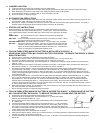
STOP/GO LITE INSTRUCTIONS
When used properly, the STOP/GO LITE will indicate whether clamp connections will be correct.
Connect the positive (red) clamp to the positive (POS, P, +) battery post. Touch the contact button
of the negative (black) clamp to the other battery post. Observe the L.E.D. lights in the STOP/GO
LITE:
GREEN LIGHT: The first connection is correct. Make the second clamp connection per
instructions.
RED LIGHT: The first connection made with the positive clamp to the battery is incorrect. Attach
the positive clamp to the other battery post and retest.
RED AND GREEN LIGHT: The battery charger is turned on. Turn the charger "OFF" and retest.
NO LIGHT: Check for a shorted or open battery. Clean any corrosion from the clamp jaws and
the battery post and retest. If still no light, use a voltmeter or other means to make
certain you have properly identified the polarity of the battery post. Then attach the
clamps per instructions, disregarding the STOP/GO LITE.
18.
FOLLOW THESE STEPS WHEN THE BATTERY IS INSTALLED IN A VEHICLE. A
SPARK NEAR THE BATTERY MAY CAUSE A BATTERY EXPLOSION. TO REDUCE THE RISK OF A SPARK
NEAR THE BATTERY:
a. Read the section "STOP/GO LITE INSTRUCTIONS" before proceeding.
b. Position the AC and DC cords to reduce the risk of damage by the hood, door, or moving engine parts.
c. Stay clear of fan blades, belts, pulleys, and other parts that can cause injury to persons.
d. Check the polarity of the battery post. The POSITIVE (POS, P, +) battery post usually has a larger diameter than the NEGATIVE
(NEG, N, -) post.
e. Determine which post of the battery is grounded (connected) to the chassis. If the negative post is grounded to the chassis (as in
most vehicles), see item "e". If the positive post is grounded to the chassis, see item "f".
f. For negative-grounded vehicles, connect the POSITIVE (RED) clamp from the battery charger to the POSITIVE (POS, P, +)
ungrounded post of the battery. Touch the contact button of the STOP/GO LITE to the NEGATIVE (NEG, N, -) battery post.
Interpret the light and take appropriate action. When the green light is on, connect the NEGATIVE (BLACK) clamp to the vehicle
chassis, heavy gauge metal part of the frame, or engine block, away from the battery. Do not connect to the carburetor, fuel lines, or
sheet metal body parts.
g. For positive-grounded vehicles, connect the POSITIVE (RED) clamp from the battery charger to the POSITIVE (POS, P, +) battery
post. Touch the contact button of the STOP/GO LITE to the NEGATIVE (NEG, N, -) battery post. Interpret the light and take
appropriate action. When the green light is on, disconnect the POSITIVE (RED) clamp from the battery. Attach the NEGATIVE
(BLACK) clamp to the NEGATIVE (NEG, N, -) ungrounded post of the battery. Attach the POSITIVE (RED) clamp to the vehicle
chassis or engine away from the battery. Do not connect the clamp to the carburetor, fuel lines, or sheet-metal body parts. Connect
to a heavy gauge metal part of the frame or engine block.
h. When disconnecting the charger, turn the switches to OFF, disconnect the AC cord, remove the clamp from the vehicle chassis, and
then remove the clamp from the battery terminal.
i. See the operating instructions for length of charge information.
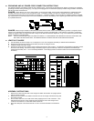
19.
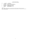
FOLLOW THESE STEPS WHEN THE BATTERY IS OUTSIDE THE VEHICLE. A SPARK NEAR THE BATTERY
MAY CAUSE BATTERY EXPLOSION. TO REDUCE THE RISK OF A SPARK NEAR THE BATTERY:
a. Read section "STOP/GO LITE INSTRUCTIONS" before proceeding.
b. Check the polarity of the battery post. The POSITIVE (POS, P, +) usually has a larger
diameter than the NEGATIVE (NEG, N, -) post.
c. Attach at least a 24 inch long 6-gauge (AWG) insulated battery cable to the NEGATIVE (NEG,
N, -) battery post.
d. Connect the POSITIVE (RED) charger clamp to the POSITIVE (POS, P, +) post of the battery.
e. Touch the contact button of the STOP/GO LITE to the free end of the battery cable. If the red
light comes on, reverse the connections to the battery and retest. When the green light come
on, position yourself and the free end of the cable as far away from the battery as possible, then connect the NEGATIVE (BLACK)
charger clamp to the free end of cable.
f. Do not face the battery when making the final connection.
g. When disconnecting the charger, always do so in reverse sequence of connecting procedure, and break the first connection while
standing as far away from the battery as practical.
h. A marine (boat) battery must be removed and charged on shore. To charge it on board requires equipment specially designed for
marine use.