


724-746-5500 | blackbox.com
Page 8
724-746-5500 | blackbox.com
4-Port CAT5 USB 2.0 Extender
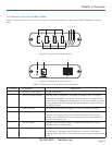
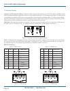
1 2 3 4
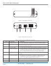
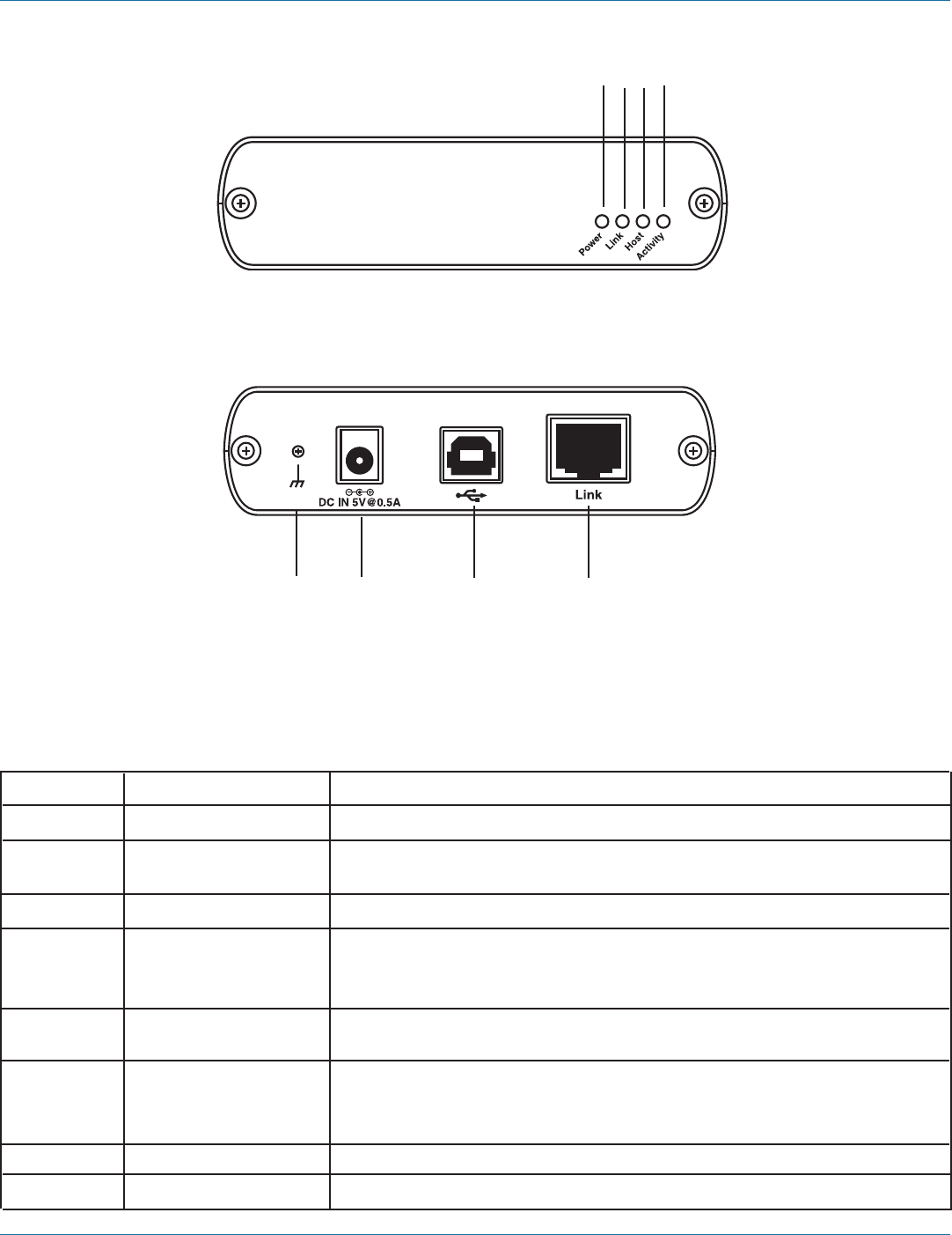
Figure 2-1. Front panel of the local unit.
5 6 7 8
Figure 2-2. Back panel of the local unit.
Table 2-1. Local unit’s front- and back-panel components.
Number Component Description
1 Power LED (blue) LED lights when power is supplied. LED is off when no power is supplied.
2 Link LED (green) LED lights when a link is established between the local unit and the
remote unit over the CAT5 cable.
3 Host LED (green) LED lights when the extender system is properly enumerated on the host PC.
4 Activity LED (amber) LED lights when data is transmitted between the local unit and remote unit.
The LED blinks intermittently with or without a USB device connected. The
LED is off when the local unit and remote unit are in suspend mode.
5 Earth ground Optional earth ground connection to housing of unit. Accepts an M2 type
screw.
6 Power port (optional) Not required in normal operation. An optional 5 V power supply can be
connected to the local unit to provide power if the USB port on the
host PC is not capable of delivering 500 mA to the unit.
7 USB Type B connector Connects the local unit to the host computer.
8 Link port (RJ-45) Accepts RJ-45 connector for CAT5 cabling (or better).