


724-746-5500 | blackbox.com
724-746-5500 | blackbox.com
Page 9
Chapter 2: Overview
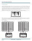
2.4.2 Remote unit Front and Back Panels
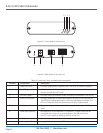
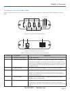
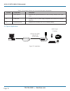
Figure 2-3 shows the remote unit’s front panel. Figure 2-4 shows the remote unit’s back panel. Table 2-2 describes its compo-
nents.
1
2 3 4 5 6
Figure 2-3. Front panel of the remote unit.
7 8 9
Figure 2-4. Back panel of the remote unit.
Table 2-2. Remote unit’s front- and back-panel components.
Number Component Description
1 Device port (USB Type A) Accepts USB device(s).
2 Device LED (green/orange) Indicates when a USB device is connected to the device port. Solid green
when device is plugged in and active. Off when device is in suspend mode
or remote unit is powered off. Orange when the remote unit detects an over-
current condition, and the attached USB device attempts to draw more than
the 500 mA current.
3 Power LED (blue) LED turns on when power is supplied. Off when no power is supplied.
4 Link LED (green) Indicates a valid USB link is established between the local unit and remote
unit over CAT5 cabling. LED turns on when link between local unit and
remote unit is established. LED turns off when there is no link between the
local unit and remote unit.
5 Host LED (green) Indicates that the extender system is properly enumerated on the host PC.
LED blinks when in suspend state.
6 Activity LED (amber) Indicates activity when data transmission is active between the local unit and
the remote unit. LED blinks intermittently with or without a USB device
attached. When the local unit and remote unit are in suspend mode, the LED
is off.