


2
• Fallback Switch (FBS), Industrial
• (1) modular 25-pin adapter (for the control port)
• (1) 6-ft. (1.8-m) 4-wire straight-through modular cable (for
connecting a DB25 terminal/PC connector to a single switch)
• (1) power cord
NOTE: If you use a PC with a 9-pin connector, you’ll need a a special
adapter. Also, to cable a terminal or PC directly to a group of
switches, use a DB25 ribbon cable. For ordering information on
these, contact Black Box Tech Support.
Approvals: FCC Part 15, UL
®
, CSA,
CE
Leads Supported: 1 through 25
Maximum Data Rate: Depends
upon cabling
Switches: (1) 2-position mode
selector
Energy Rate: 6 VA
Receptacle: 3-prong grounding
Interface: SW111A: RS-232/V.24;
SW115A: V.35;
SW116A: RS-530
Connectors: All: (1) 8-pin RJ-45;
SW111A, SW116A: (3) DB25 F;
SW115A: (3) M/34 F
Indicators: (1) A, (1) B, (1) SD, (1) RD,
(1) CD, (1) DTR, (1) RTS
Power: 100–120 VAC, 60 Hz
Size: 1.6"H x 8.4"W x 10.8"D
(4.1 x 21.3 x 27.4 cm)
Weight: 4.8 lb. (2.2 kg)
What’s included
Specifications
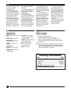
Ordering Information
ITEM CODE
Fallback Switch (FBS), Industrial
RS-232/V.24..............................................................SW111A
V.35 ............................................................................SW115A
RS-530.......................................................................SW116A
Y
ou might also want to order cables:
RS-232 Cable (NEC
®
CL2)........................ECM25C-0010-MF
side and a return of carrier detect
on “A” triggers automatic
switching back to “A.”
The Fallback Switch even
enables you to specify at what
point an alarm is reported. Set it up
so the condition causing the alarm
must be present for a certain
period of time (the “Time to
Alarm”) before the switch sends
an alarm to the console. Likewise,
you can also specify the time it
takes to clear an alarm that‘s
reported. With this function, the
switch issues a “clear” report after
the original alarm condition has
been clear for a user-definable
period of time.
Console-controlled data circuit
alarming on both “A” and “B”
connectors occurs independent
of switch position.
Console-driven operation
To determine the status of any
interface or switch the circuit, just
access the Fallback Switch
through the management console
connection. You can view the
physical-layer status of eight
signals on the “A” connector and
on the “B” connector regardless
of the current switch position.
User-friendly help screens
guide you through the process,
and you use password-protected
menus to access groups of switch
commands.
These include groups for
displaying and configuring switch
alarms and defining alarms per
interface; for switching and
displaying switch status; and for
turning on or off the leads status
display on the management
console. You can even disable
front-panel control to ensure that
all switching control comes from
the console’s user.
Also use the console menus
to set up remote control of the
Fallback Switch through a modem
connection. The switch can be
programmed to use this modem
link to automatically dial a remote
management terminal when an
alarm occurs and ”hang up” the
modem when the transmission is
completed.
The Fallback Switch stores all
configuration-related commands,
including switch settings, in
battery-backed RAM.