


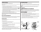
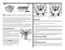


sketch B if a properly grounded outlet is not available. The temporary adapter should be used only
until a properly grounded outlet can be installed by a qualified electrician. The green-colored rigid ear,
lug, and the like, extending from the adapter must be connected to a permanent ground such as a
properly grounded outlet box.
ADAPTER SHOWN IN FIGURES B & C IS NOT FOR USE IN CANADA.
Extension Cords
Tools that have 3 wire cords requiring grounding must only be used with extension cords that have 3-
prong grounding type plugs and 3-pole receptacles. Only round jacketed extension cords should be
used, and we recommend that they be listed by Underwriters Laboratories (U.L.) (C.S.A. in Canada). If
the extension will be used outside, the cord must be suitable for outdoor use. The letters “WA” on the
cord jacket indicate that it is suitable for outdoor use. Any cord marked as outdoor can also be used
for indoor work.
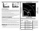
An extension cord must have adequate wire size (AWG or American Wire Gauge) for safety, and to
prevent loss of power and overheating. The smaller the gauge number of the wire, the greater the
capacity of the cable, that is 16 gauge has more capacity than 18 gauge. When using more than one
extension to make up the total length, be sure each individual extension contains at least the mini-
mum wire size. To determine the minimum wire size required, refer to the following chart:
1
1
2
2
0
0
V
V
O
O
L
L
T
T
T
T
O
O
O
O
L
L
S
S
: CHART FOR MINIMUM WIRE SIZE (AWG) OF EXTENSION CORDS
Cord Length (feet) 25 50 75 100
Guage: 16 14 12 10
Before using an extension cord, inspect it for loose or exposed wires, damaged insulation, and
defective fittings. Make any needed repairs or replace the cord if necessary. B&D has extension
cords available that are U.L. (C.S.A. in Canada) listed for outdoor use.
Unpacking Your Saw
Check the contents of your miter saw carton to make sure that you have received all parts. In addition
to this instruction manual, the carton should contain: one 3680 miter saw, one carbide saw blade
and one blade wrench in wrench pocket.
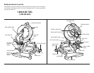
Familiarization
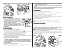
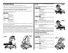
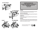
Your miter saw is fully assembled in the carton. Open the box and lift the saw out by the convenient
carrying handle, as shown in Figure 1. Place the saw on a smooth, flat surface such as a workbench or
strong table. Examine Figures on inside front cover of this manual to become familiar with the saw
and its various parts. The following section on adjust-
ments will refer to these terms and you must know what
the parts are.
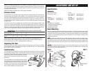
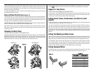
Press down lightly on the operating handle and pull out
the lock down pin, as shown in Figure 2. Gently release
the downward pressure and allow the arm to rise to its
full height. Use the lock down pin when carrying the saw
from one place to another. Always use the carrying han-
dle or the hand indentations to transport the saw.
Specifications
C
C
a
a
p
p
a
a
c
c
i
i
t
t
y
y
o
o
f
f
c
c
u
u
t
t
48˚ miter left and right 0˚ miter
48˚ bevel left: 3˚ right Max. Height 3.9" Result Width 5.9"
Max. Width 7.9" Result Height 2.5"
45˚ miter 45˚ bevel
Max. Height 3.9" Result Width 4.1" Max. Height 2.7” Result Width 5.9”
Max. Width 5.5" Result Height 2.5" Max Width 7.9” Result Height 1.7”
D
D
r
r
i
i
v
v
e
e
2000 Watts out 13 Amp Motor
Cut Helical Gears with Ball Bearings
Carbide Blade, 4000 RPM
Automatic Electric Brake
Bench Mounting
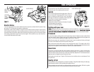
Holes are provided in all four feet to facilitate bench mounting. (Two different sized holes are provided
to accommodate different sizes of screws. Use either hole, it is not necessary to use both.) Always
mount your saw firmly to prevent movement. To enhance the tool’s portability, it can be mounted to a
piece of 1/2” or thicker plywood which can then be clamped to your work support or moved to other
job sites and reclamped.
N
N
O
O
T
T
E
E
:
:
If you elect to mount your saw to a piece of plywood, make sure that the mounting screws
don’t protrude from the bottom of the wood. The plywood must sit flush on the work support. When
clamping the saw to any work surface, clamp only on the clamping bosses where the mounting screw
holes are located. Clamping at any other point will surely interfere with the proper operation of the
saw.
C
C
A
A
U
U
T
T
I
I
O
O
N
N
:
:
To prevent binding and inaccuracy, be sure the mounting surface is not warped or other-
wise uneven. If the saw rocks on the surface, place a thin piece of material under one saw foot until
the saw sits firmly on the mounting surface.
3
F
F
i
i
g
g
u
u
r
r
e
e
1
1
F
F
i
i
g
g
u
u
r
r
e
e
2
2
F
F
i
i
g
g
u
u
r
r
e
e
3
3
LOCK DOWN
PIN
GUARD BRACKET
SCREW
ADJUSTMENT AND SET UP