


•
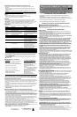
To remove the contour sanding piece, push it forward then pull the rear end out of
the profile holder (fig. 7).
Fitting a Sanding Sheet Onto a Contour Sanding Piece (Fig. 8)
• Align the sanding sheet with the contour sanding piece.
• Press the sanding sheet onto the contour sanding piece, making
sure that the sanding sheet follows the shape of the profile.
M a i n t e n a n c e
Use only mild soap and damp cloth to clean the tool. Never let any liquid get inside the tool;
never immerse any part of the tool into a liquid.
I M P O R TA N T: To assure product SAFETY and RELIABILITY, repairs, maintenance and
adjustment should be performed by authorized service centers or other qualified service
organizations, always using identical replacement parts.
A c c e s s o r i e s
Look for the following Mouse
T M
accessories at your local retailer.
Catalog # D e s c r i p t i o n C o n t e n t s
7 4 - 5 8 3 120 Medium Sandpaper 5 sheets
7 4 - 5 8 4 180 Fine Sandpaper 5 sheets
7 4 - 5 8 5 220 Extra Fine Sandpaper 5 sheets
7 4 - 5 8 6 Sandpaper A s s o r t m e n t 1 sheet of 120 grit paper, 2 sheets each 180,
220 paper
7 4 - 5 8 7 Finger Attachment Paper 5 fingers each of 120, 180, 220
7 4 - 5 8 8 1 OT Power Wo o l 3 sheets
7 4 - 5 8 9 4 OT Power Wo o l 3 sheets
7 4 - 5 8 1 Polishing Kit 2 sheets of 1 OT power wool, 2 sheets of 4 OT
power wool, 2 foam pads
7 4 - 5 8 2 Scrubbing Kit 2 coarse abrasive pads, 2 fine abrasive pads,
2 foam pads
7 4 - 5 8 0 Sanding/Polishing Kit 2 sheets of 1 OT power wool, 2 sheets of 180
grit sandpaper, 2 sheets of 240 grit sandpaper,
2 foam pads, 5 finger attachment paper
7 4 - 6 7 1 Cyclone Sandpaper/Coarse 5 sheets of 80 grit
7 4 - 6 7 2 C y c l o n e S a n d p a p e r / M e d . 5 sheets of 120 grit
7 4 - 6 7 3 C y c l o n e S a n d p a p e r / F i n e 5 sheets of 220 grit
7 4 - 6 7 4 C y c l o n e S a n d p a p e r A s s o r t m e n t
Recommended accessories for use with your tool are available at extra cost. Listings per
retailer may vary. The hook and loop pad and individual bases are replaceable parts. If they
become worn, contact your local service center. For more information call:
1 - 8 0 0 - 5 4 4 - 6 9 8 6 .
WA R N I N G : The use of any accessory not recommended for use with this tool could be
h a z a r d o u s .
Application / Accessory Matrix
A C C E S S O R Y R E C O M M E N D E D A P P L I C AT I O N S / U S E S
ME D I U M G R I T S A N D P A P E R PA I N T, VA R N I S H , RU S T RE M O VA L
F
I N E G R I T S A N D PA P E R
S
U R FA C E B L E N D I N G A N D F I N I S H I N G
E
X T R A
F
I N E G R I T S A N D PA P E R
S
A N D I N G B E T W E E N C O AT S O F PA I N T O R VA R N I S H
D
E TA I L S A N D I N G T I P S
C
O R N E R S
/ H
A R D TO R E A C H P L A C E S
1 OT
P O L I S H I N G
/ S
T R I P P I N G W O O L
P
O L I S H I N G M E T A L S
/ S
T R I P P I N G VA R N I S H O R U R E T H A N E
4 OT F I N E P O L I S H I N G W O O L F I N E P O L I S H I N G , S AT I N F I N I S H O N PA I N T / VA R N I S H / U R E T H A N E
G R E Y F O A M PA D A P P LY I N G A N D R E M O V I N G P O L I S H
W H I T E N O N
-
W O V E N PA D L I G H T S C R U B B I N G
R E D N O N -W O V E N PA D H E AV Y S C R U B B I N G / R U S T R E M O VA L
The pads described above are available in kits where Mouse products are sold, The hook
and loop pad and individual bases are replaceable parts. If they become worn, contact your
local service center. For more information call 1 - 8 0 0 - 5 4 4 - 6 9 8 6.
Service Information
Black & Decker offers a full network of company-owned and authorized service locations
throughout North America. All Black & Decker Service Centers are staffed with trained
personnel to provide customers with efficient and reliable power tool service.
Whether you need technical advice, repair, or genuine factory replacement parts, contact the
Black & Decker location nearest you.
To find your local service location, refer to the yellow page directory under "To o l s — E l e c t r i c "
or call: 1 - 8 0 0 - 5 4 4 - 6 9 8 6 .
Full Tw o - Year Home Use Wa r r a n t y
Black & Decker (U.S.) Inc. warrants this product for two years against any defects in material
or workmanship. The defective product will be replaced or repaired at no charge in either of
two ways.
The first, which will result in exchanges only, is to return the product to the retailer from
whom it was purchased (provided that the store is a participating retailer). Returns should be
made within the time period of the retailer’s policy for exchanges (usually 30 to 90 days after
the sale). Proof of purchase may be required. Please check with the retailer for their specific
return policy regarding returns that are beyond the time set for exchanges.
The second option is to take or send the product (prepaid) to a Black & Decker owned or
authorized Service Center for repair or replacement at our option. Proof of purchase may be
required. Black & Decker owned and authorized Service Centers are listed under "To o l s -
Electric" in the yellow pages of the phone directory and on our website
w w w. b l a c k a n d d e c k e r. c o m .
This warranty does not apply to accessories. This warranty gives you specific legal rights
and you may have other rights which vary from state to state. Should you have any
questions, contact the manager of your nearest Black & Decker Service Center. This product
is not intended for commercial use.
FREE WARNING LABEL R E P L A C E M E N T: If your warning labels become illegible or are
missing, call 1-800-544-6986 for a free replacement.
See ‘Tools-Electric’
– Yellow Pages –
for Service & Sales
Black & Decker (U.S.) Inc.,
701 E. Joppa Rd.
Towson, MD 21286 U.S.A.
Safety Warnings and Instructions: Sanders
• A LWAYS WEAR EYE AND RESPIRATO RY P R O T E C T I O N .
• Clean your tool out periodically.
Other Important Safety Warnings and Instructions
Extension Cord s
When using an extension cord, be sure to use one heavy enough to carry the current your
product will draw. An undersized cord will cause a drop in line voltage resulting in loss of
power and overheating. The following table shows the correct size to use depending on cord
length and nameplate ampere rating. If in doubt, use the next heavier gage. The smaller the
gage number, the heavier the cord.
Sanding
Lead Based Paint
Sanding of lead based paint is NOT RECOMMENDED due to the difficulty of controlling the
contaminated dust. The greatest danger of lead poisoning is to children and pregnant
w o m e n .
Since it is difficult to identify whether or not a paint contains lead without a chemical analysis,
we recommend the following precautions when sanding any paint:
Personal Safety
• No children or pregnant women should enter the work area where the paint sanding is
being done until all clean up is completed.
• A dust mask or respirator should be worn by all persons entering the work area. The filter
should be replaced daily or whenever the wearer has difficulty breathing.
• NOTE: Only those dust masks suitable for working with lead paint dust and fumes should
be used. Ordinary painting masks do not offer this protection. See your local hardware
dealer for the proper (NIOSH approved) mask.
• NO EATING, DRINKING or SMOKING should be done in the work area to prevent
ingesting contaminated paint particles. Workers should wash and clean up BEFORE
eating, drinking or smoking. Articles of food, drink, or smoking should not be left in the work
area where dust would settle on them.
Environmental Safety
• Paint should be removed in such a manner as to minimize the amount of dust generated.
• Areas where paint removal is occurring should be sealed with plastic sheeting of 4 mils
t h i c k n e s s .
• Sanding should be done in a manner to reduce tracking of paint dust outside the work
a r e a .
Cleaning and Disposal
• All surfaces in the work area should be vacuumed and thoroughly cleaned daily for the
duration of the sanding project. Vacuum filter bags should be changed frequently.
• Plastic drop cloths should be gathered up and disposed of along with any dust chips or
other removal debris. They should be placed in sealed refuse receptacles and disposed of
through regular trash pick-up procedures. During clean up, children and pregnant women
should be kept away from the immediate work area.
• All toys, washable furniture and utensils used by children should be washed thoroughly
before being used again.
M o t o r
Be sure your power supply agrees with nameplate marking. 120 Volts AC only means your
tool will operate on standard 60 Hz household power. Do not operate AC tools on DC. A
rating of 120 volts AC/DC means that you tool will operate on standard 60 Hz AC or DC
p o w e r. This information is printed on the nameplate. Lower voltage will cause loss of power
and can result in over-heating. All Black & Decker tools are factory-tested; if this tool does
not operate, check the power supply.
Operating Instructions
WARNING: To reduce the risk of serious personal injury, read, understand and follow all
important safety warnings and instructions prior to using this tool.
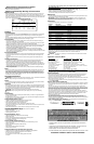
Switch
To turn the tool ON, hold it as shown in Figure 1 and push the portion of the switch marked
"I". To turn the tool OFF, push the portion of the switch marked "O".
O p e r a t i o n
Grasp product as shown in Figure 1 and turn it on. Move it in long sweeping strokes across
the surface, letting it do the work. Light pressure is all that is required for sanding, polishing
or scrubbing. Excessive pressure will slow the tool and produce inferior results. Check your
work often, product is capable of removing material rapidly.
CAUTION: Under no circumstances should this product be used near water.
WARNING: Always unplug product from power supply before any of the following
operations.
Detail Sanding
Your tool is equipped with a teardrop base which allows you to use it on large flat surfaces
and tight spots or corners.
The pad tips may wear unevenly, depending on use. The pads are designed to allow you to
interchange and /or rotate the diamond tip.
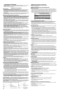
Fitting Sanding Sheets ( Fig. 2)
• Detach the two diamond-shaped tips from the sanding sheet.
• Hold the tool with the sanding base facing upwards.
• Place the sanding sheet onto the sanding base.
The diamond-shaped tip can be reversed and replaced when worn.
• When the front part of the tip is worn, detach it from the sheet, reverse it and press it onto
the sanding base again.
• When the whole tip is worn, remove it from the sanding base and fit a new tip.
Tip of the Sanding Base ( Fig. 3)
When the sanding base tip is worn, it can be reversed or replaced.
• Remove the screw.
• Reverse or replace the worn part.
• Fit and tighten the screw.
Finger Attachment ( Fig. 4)
The finger attachment is used for fine detail sanding.
• Remove the screw.
• Remove the diamond-shaped tip holder from the sanding base.
• Fit the finger attachment onto the sanding base.
• Fit and tighten the screw.
Contour Holder Attachment (Fig. 5)
• The contour sanding pieces are for sanding curved surfaces and grooves.
• Remove the screw.
• Remove the diamond-shaped tip holder from the
sanding base.
• Fit the contour holder onto the sanding base.
• Fit and tighten the screw.
Fitting and Removing a Contour Piece (Fig. 6 & 7)
• Choose the contour sanding piece profile most suitable for your application.
• Place one end of the contour sanding piece into the recess at
the front end of the profile holder.
• Push the other end of the contour sanding piece until it clicks
into place.
Minimum Gage for Cord Sets
Volts Total Length of Cord in Feet
120V 0-25 26-50 51-100 101-150
240V 0-50 51-100 101-200 201-300
Ampere Rating
More Not more American Wire Gage
Than Than
0 - 6 18 16 16 14
6 - 10 18 16 14 12
10 - 12 16 16 14 12
12 - 16 14 12 Not Recommended
RENSEIGNEMENTS IMPORTA N T S
• Ne jamais utiliser l’outil sans le papier abrasif recommandé bien installé sur le
socle muni.
• Le tampon les socles individuels peuvent être remplacés. Lorsqu’ils sont usés,
confier la réparation de l’outil au personnel d’un centre de service.
• Ne pas appuyer sur l’outil; laisser la ponceuse faire le travail.
• Il est déconseillé de poncer pendant de longues durées des murs secs avec l’outil.
C O N S E R VER LE PRÉSENT GUIDE À TITRE DE RÉFÉRENCE.