


OperationUSE
WARNING: Laceration Hazard. To prevent loss of control, never use the tool when
the saw shoe is loose or removed. Failure to do this could result in serious personal injury.
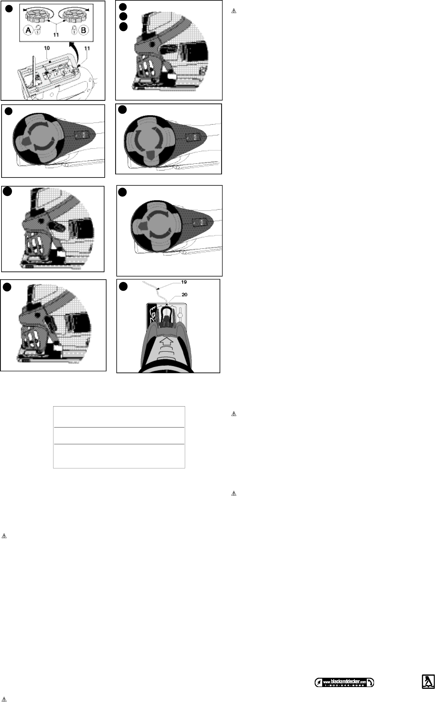
Adjusting the shoe plate for bevel cuts (fig. E)
The shoe plate can be set to a left or right bevel angle of up to 45°.
- Turn the locking knob (11) in direction A to release the shoe plate (10).
- Pull the shoe plate (10) backwards and set it to the required angle. You can use the
scale or a protractor to check the angle.
- Turn the locking knob (11) in direction B to lock the shoe plate in place.
To reset the shoe plate for straight cuts:
- Turn the locking knob (11) in direction A to release the shoe plate (10).
- Pull the shoe plate backwards and set it to an angle of approximately 0.
- Push the shoe plate forward.
- Turn the locking knob (11) in direction B to lock the shoe plate in place. Make sure that
the shoe plate is supported by the guide ribs.
Variable speed control
- Set the variable speed control knob (3) to the required speed range. Use a high speed
for wood, medium speed for aluminum and PVC and low speed for metals other than
aluminum.
Switching On and Off
- To switch the tool on, press the on/off switch (1).
- For continuous operation, press the lock-on button (2) and release the on/off switch.
- To switch the tool off, release the on/off switch. To switch the tool off, when in continuous
operation, press the on/off switch once more and release it.
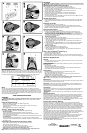
Using the mode selector
The mode selector (9) can set in 3 positions
1. Scrolling position (figs F and G) - this position allows the scroller knob (8) to be
rotated for intricate and accurate sawing. (In this position there is no orbital action.)
It is recommended to use scroller blades when in this mode.
2. Straight cutting position (figs Ha, Hb and Hc ) this position turns off orbital action and
locks the scroller knob to prevent its rotation. The scroller knob can be locked in any
of 4 positions for straight cutting.
Method of engagement:
a. Turn the Mode Selector to the scrolling position.
b. Rotate the scroller knob to the desired position (this can be any of 4 positions - the
blade can point forwards, reverse, left or right).
c. Turn the Mode Selector to the neutral position. (In this position the Scroller Knob
cannot be turned).
3. Orbital Action Position (figs Ia, Ib and Ic) - this position switches on the orbital action
for fast and efficient straight cuts. This mode can only be selected with the blade
pointing forwards.
Method of engagement:
a. Turn the mode selector to the scrolling position.
b. Rotate the scroller knob to point the blade forwards.
c. Turn the Mode Selector to the orbital position. (In this position the Scroller Knob
cannot be turned).
How to Use the Sightline
®
Feature (fig. J)
- Use a pencil to mark the cutting line.
- Position the jigsaw over the line (19).
Viewing from directly above the jigsaw the line of cut can be easily followed. Should this
view be restricted for any reason, the indent (20) can be used as an alternate cutting guide.
Hints for Optimum Use
General
- Use a high speed for wood, a medium speed for aluminum and PVC and a low speed
for metals other than aluminum.
Sawing laminates
As the saw blade cuts on the upward stroke, splintering may occur on the surface closest
to the shoe plate.
- Use a fine-tooth saw blade.
- Saw from the back surface of the workpiece.
- To minimize splintering, clamp a piece of scrap wood or hardboard to both sides of
the workpiece and saw through this sandwich.
Sawing metal
- Be aware that sawing metal takes much more time than sawing wood.
- Use a saw blade suitable for sawing metal.
- When cutting thin metal, clamp a piece of scrap wood to the back surface of the
workpiece and cut through this sandwich.
- Spread a film of oil along the intended line of cut.
WARNING: Fire Hazard. Do not use vacuum adapter when cutting metal. Metal
filings will be hot and could cause a fire in the vacuum container.
Maintenance
Use only mild soap and damp cloth to clean the tool. Never let any liquid get inside the tool;
never immerse any part of the tool into a liquid.
IMPORTANT: To assure product SAFETY and RELIABILITY, repairs, maintenance and
adjustment should be performed by authorized service centers or other qualified service
personnel, always using identical replacement parts.
Accessories
Recommended accessories for use with your tool are available from your local dealer or
authorized service center. If you need assistance regarding accessories, please call:
1-800-544-6986.
WARNING: The use of any accessory not recommended for use with this tool could be
hazardous.
Service Information
Black & Decker offers a full network of company-owned and authorized service locations
throughout North America. All Black & Decker Service Centers are staffed with trained
personnel to provide customers with efficient and reliable power tool service. Whether you
need technical advice, repair, or genuine factory replacement parts, contact the
Black & Decker location nearest you. To find your local service location, refer to the yellow
page directory under "Tools—Electric" or call: 1-800-544-6986.
Full Two-Year Home Use Warranty
Black & Decker (U.S.) Inc. warrants this product for two years against any defects in
material or workmanship. The defective product will be replaced or repaired at no charge in
either of two ways. The first, which will result in exchanges only, is to return the product to
the retailer from whom it was purchased (provided that the store is a participating retailer).
Returns should be made within the time period of the retailer’s policy for exchanges (usually
30 to 90 days after the sale). Proof of purchase may be required. Please check with the
retailer for their specific return policy regarding returns that are beyond the time set for
exchanges.
The second option is to take or send the product (prepaid) to a Black & Decker owned or
authorized Service Center for repair or replacement at our option. Proof of purchase may be
required. Black & Decker owned and authorized Service Centers are listed under
"Tools–Electric" in the yellow pages of the phone directory.
This warranty does not apply to accessories. This warranty gives you specific legal rights
and you may have other rights which vary from state to state. Should you have any
questions, contact the manager of your nearest Black & Decker Service Center.
This product is not intended for commercial use.
Free Warning Label Replacement: If your warning labels become illegible or are missing,
call 1-800-544-6986 for a free replacement.
Motor
Be sure your power supply agrees with nameplate marking. 120 Volts AC only means
your tool will operate on standard 60 Hz household power. Do not operate AC tools on DC.
A rating of 120 volts AC/DC means that you tool will operate on standard 60 Hz AC or DC
power. This information is printed on the nameplate. Lower voltage will cause loss of power
and can result in over-heating. All Black & Decker tools are factory-tested; if this tool does
not operate, check the power supply.
SAVE THESE INSTRUCTIONS
Assembly
WARNING: Sharp blade. To prevent accidental operation, turn off and unplug saw
before performing the following operations. Failure to do this could result in serious
personal injury.
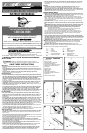
Fitting the saw blade (fig. A)
- Hold the saw blade (7) as shown, with teeth facing forward.
- Push the lever (4) downwards.
- Insert the shank of the saw blade into the blade holder (15) as far as it will go.
- Release the lever.
- Adjust the blade support roller as described below.
AccuCut
TM
blade support roller (fig. B)
After fitting the blade, you need to adjust the blade support roller (5).
Screwdriver Method
- Turn the slotted blade support adjustment screw (6) in direction A.
- Slide the blade support roller against the rear of the blade. The blade must locate
in the central recess of the roller.
- Turn the blade support adjustment screw in direction B to lock the blade support in place.
Tool Free Method
- The blade support roller can be adjusted in a “tool free” manner, by turning the scroll
ing knob (8) so that the adjustment screw is rotated around to the front of the unit where it can
be turned by hand.
Connecting a vacuum cleaner to the tool (fig. C & D)
- Align the dust extraction adaptor (14) with the saw shoe as shown.
- Insert the ribs (16) into the slots (17).
- Pull the adaptor towards the rear of the jigsaw to secure.
- Connect the vacuum cleaner hose (18) (not supplied) to the adaptor.
- Dust extraction is not possible when making bevel cuts.
WARNING: Fire Hazard. Do not use vacuum adapter when cutting metal. Metal
filings will be hot and could cause a fire in the vacuum container.
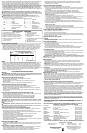
Use of Extension Cords
Make sure the extension cord is in good condition before using. Always use the proper size
extension cords with the tool – that is, proper wire size for various lengths of cord and heavy
enough to carry the current the tool will draw. Use of an undersized cord will cause a drop in
line voltage resulting in loss of power and overheating. For proper size cords see chart.
F
G
Hb
Hc
Ib
Ha
Ia
Ic
Minimum Gage for Cord Sets
Volts Total Length of Cord in Feet
120V 0-25 26-50 51-100 101-150
240V 0-50 51-100 101-200 201-300
Ampere Rating
More Not more American Wire Gage
Than Than
0 - 6 18 16 16 14
6 - 10 18 16 14 12
10 - 12 16 16 14 12
12 - 16 14 12 Not Recommended
J
See ‘Tools-Electric’
– Yellow Pages –
for Service & Sales
Imported by
Black & Decker (U.S.) Inc.,
701 E. Joppa Rd.
Towson, MD 21286 U.S.A.
E