


13
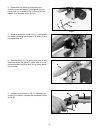
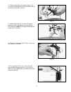
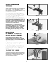
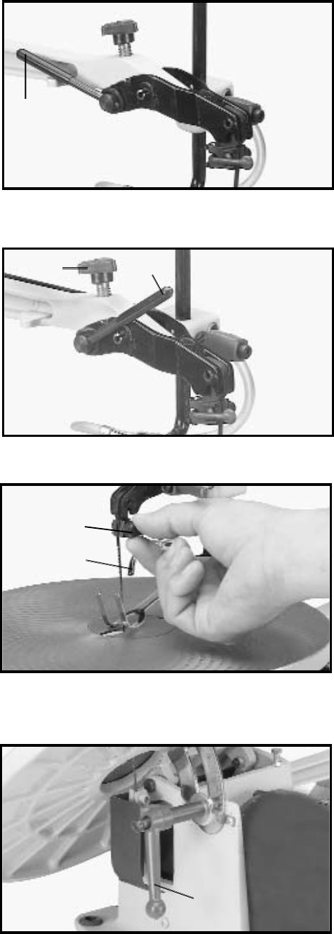
ADJUSTING BLADE
TENSION
Tension is applied to the blade when the blade tension
lever (A) Fig. 27, is in the rear position, as shown.
When the lever (A) is moved forward, as shown in Fig.
28, blade tension is released.
When adjusting blade tension, lever (A) should be in
the forward position, as shown in Fig. 28. To increase
blade tension, turn knob (B) Fig. 28, clockwise and to
decrease blade tension, turn knob (B)
counterclockwise. NOTE: It is necessary to adjust the
blade tension knob (B) only when the blade is removed
from both upper and lower blade holders and a new or
different type of blade is assembled to the holders. It is
not necessary to adjust blade tension when the blade is
removed and replaced in only the upper blade holder as
in performing inside cutting operations.
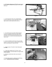
Adjusting the blade for proper tension is usually
accomplished by trial and error. One method is to pull
back on the blade tension lever (A) Fig. 28, the blade
should start to have tension (resistance) when the
blade tension lever is half way between open Fig. 28,
and closed Fig. 27. Finer blades require more
tensioning while thicker blades require less tension.
Fig. 27
Fig. 28
A
A
B
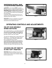
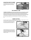
ADJUSTING
CLAMPING ACTION OF
UPPER BLADE HOLDER
Different widths of scroll saw blades will make it
necessary to adjust the clamping action of the upper
blade holder. It should be noted, however, that very little
adjustment is necessary and very little clamping force is
required to hold the blade.
1. Move the chuck locking lever (C) Fig. 23, to the
rear (open) position, as shown.
2. Turn locknut (C) Fig. 29, clockwise to tighten and
counterclockwise to loosen the clamping action of the,
blade holder. Very little movement of locknut (C) is
necessary.
Fig. 29
A
C
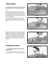
Fig. 30
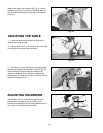
TILTING THE TABLE
The table on your scroll saw can be tilted 45 degrees to
the left for bevel cutting operations by loosening table
lock handle (A) Fig. 30, tilt the table to the desired
angle and tighten lock handle (A).
A