


44
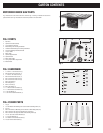
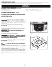
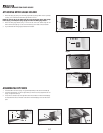
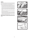
1. Attach the spring clip (E) Fig. 19 to the miter gauge holder (A) using an M4x.7x10mm pan head
screw (F), 3/16” external tooth lockwasher, (B) and M4x.7 hex nut.
NOTE: The hex nut (G) Fig. 20 will fit into the recess at the back of the miter gauge
holder (A) Fig. 19 to keep the spring clip (E) secured to the miter gauge holder.
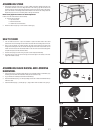
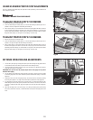
2. Attach the miter gauge holder (A) Fig. 21 to the left side of the saw cabinet using the four
M4x.2x10mm screws (B) Fig. 22, and 3/16” flat washers (C) from inside of the saw cabinet.
3. Fig. 23 illustrates the miter gauge (D) inserted into the holder.
ATTACHING MITER GAUGE HOLDER
DISCONNECT MACHINE FROM POWER SOURCE.
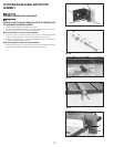
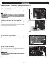
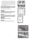
ASSEMBLING RIP FENCE
1. Thread the M8x1.25 hex nut (A) Fig. 24, approximately halfway on the stud of the handle (B).
2. Thread the handle (B) Fig. 24 into the tapped hole (C) in the fence cam (D). Tighten the hex nut
(A) Fig. 25 against the cam (D).
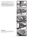
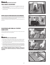
3. The rip fence is usually set up on the right hand side of the saw table. Lift the lock handle (B) Fig.
26 and position the fence on the table. Push down on the handle (B) Fig. 26 to lock the fence in
place.
Fig. 19
E
F
A
B
Fig. 20
G
Fig. 21
Fig. 22
Fig. 23
Fig. 24
A
D
C
B
D
A
B
C
Fig. 25
D
A
B