


10
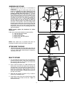
ATTACHING MITER GAUGE HOLDER
DISCONNECT MACHINE FROM POWER SOURCE.
Fig. 5
E
A
B
Fig. 6
G
F
Fig. 7
Fig. 8
Fig. 9
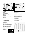
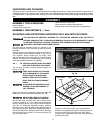
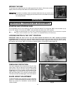
1. Attach the spring clip (E) Fig. 5 to the miter gauge holder (A) using an M4x.7x10mm pan head screw (F), 3/16"
external tooth lockwasher, (B) and M4x.7 hex nut.
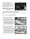
NOTE: The hex nut (G) Fig. 6 will fit into the recess at the back of the miter gauge holder (A) Fig. 5 to keep the
spring clip (E) secured to the miter gauge holder.
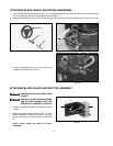
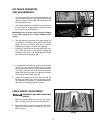
2. Attach the miter gauge holder (A) Fig. 7 to the left side of the saw cabinet using the four M4x.2x10mm screws (B)
Fig. 8, and 3/16" flat washers (C) from inside of the saw cabinet.
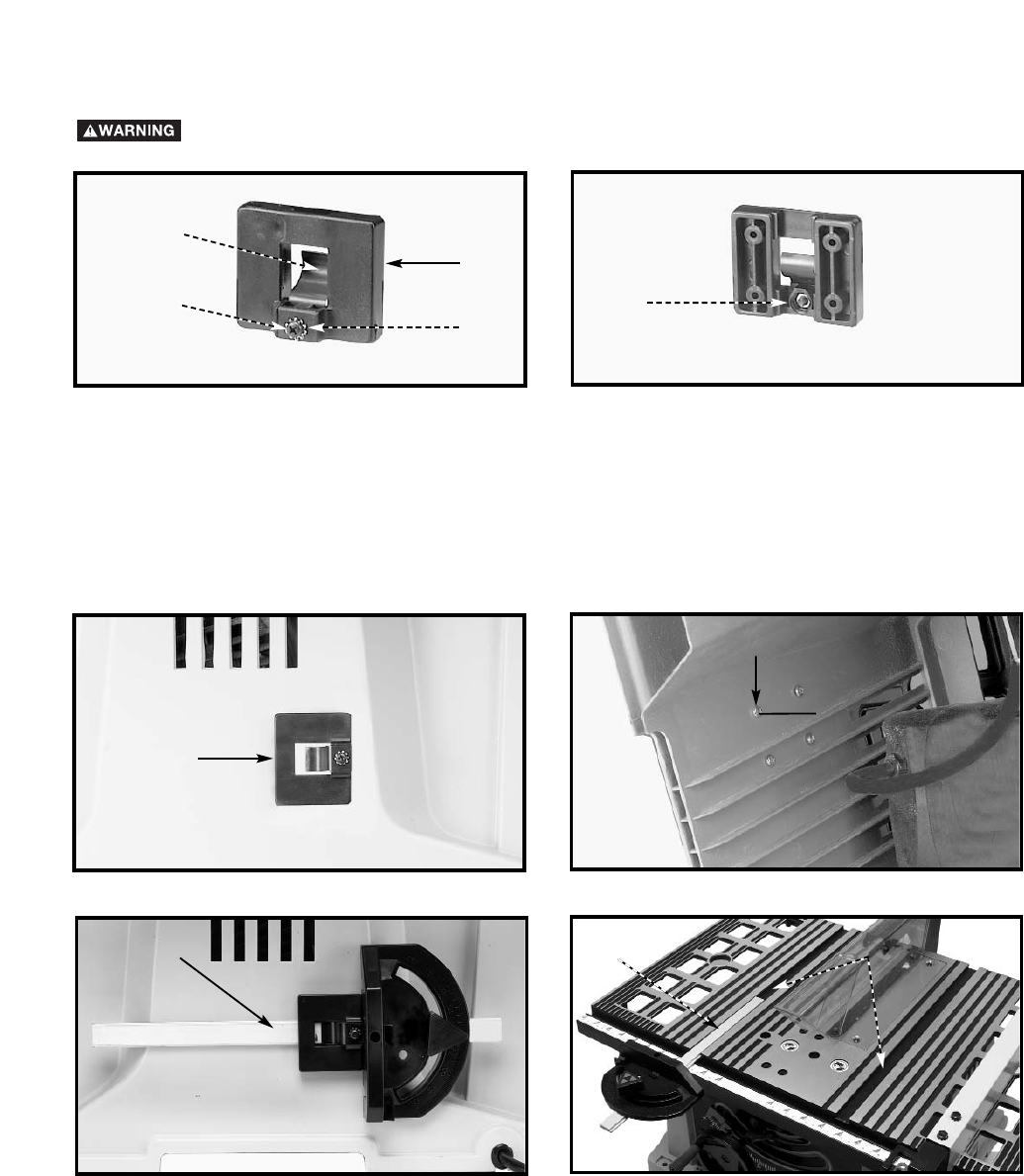
3. Fig. 9 illustrates the miter gauge (D) inserted into the holder.
A
B
C
D
Fig. 10
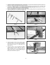
MITER GAUGE
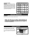
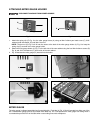
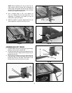
The miter gauge is shipped assembled and is supplied with a T-slot bar (A) Fig. 10 that is inserted into either one of the
two T-slotted miter gauge grooves (B) located in the table top. The T-slot prevents the miter gauge from falling when it
is extended beyond the front of the table when cross-cutting extra wide workpieces.
A
B