


15
ENGLISH
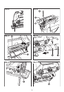
Fitting and removing the saw blade (fig. B and C)
Warning! Before attempting any of the following
operations, make sure that the tool is switched off and
unplugged and that the saw blade has stopped. Used saw
blades may be hot.
Fitting the saw blade (fig. B)
Hold the saw blade (10) as shown, with the teeth facing
forward.
Push and hold the blade clamp (11) down.
Insert the shank of the saw blade into the blade holder
(12) as far as it will go.
Release the blade clamp (11).
Saw blade storage (fig. C)
Saw blades (10) can be stored in the storage compartment (4)
located on the side of the tool.
Open the cover of the saw blade storage compartment (4)
by holding the tab on the top of the cover and pulling it
outward.
The blades are retained in the compartment by a
magnetic strip. To remove a blade, press down on one
end of the blade to raise the other end, and remove.
Close the cover of the saw blade storage compartment
(4) and make sure that it is latched closed.
Warning! Close the storage compartment door securely
before operating the saw.
Connecting a vacuum cleaner to the tool (fig. D)
An adaptor (13) is required to connect a vacuum cleaner or
dust extractor to the tool.
Push the adaptor (13) into the dust extraction outlet (6).
Connect the vacuum cleaner hose (14) to the adaptor (13).
Cut line blower (fig. E)
To aid visibility when cutting, your jigsaw is equipped with
a cut line blower (15) which will keep the work area clear
of dust as you saw.
USE
Adjusting the shoe plate for bevel cuts (fig. F and G)
Warning! Never use the tool when the shoe plate is loose
or removed.
The shoe plate (7) can be set to a left or right bevel angle of
up to 45°.
Pull the shoe plate locking lever (5) outwards to unlock
the shoe plate (7) from the 0 deg position.
Pull the shoe plate (7) forward and set the required bevel
15°, 30° and 45° indicated in the bevel angle window.
Push the shoe plate locking lever (5) back towards the
saw to lock the shoe plate (7).
To reset the shoe plate (7) for straight cuts:
Pull the shoe plate locking lever (5) outwards to unlock
the shoe plate (7).
Set the shoe plate (7) to an angle of 0° and push the shoe
plate backwards.
Push the shoe plate locking lever (5) back towards the
saw to lock the shoe plate (7).
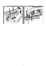
Setting the pendulum stroke (fig. H)
Set the pendulum stroke selector (9) to the required
position.
Position 0: metal and aluminium and sheet metal.
Position I: for laminates, hard wood, work tops.
Position II: for plywood and PVC/Plastics.
Position III: for soft wood and fast cutting.
Variable speed control
Set the variable speed control knob (1) to the required
speed range.
Use a high speed for wood, medium speed for aluminium
and PVC and low speed for metals other than aluminium.
Switching on and off
To switch the tool on, press the on/off switch (2).
To switch the tool off, release the on/off switch (2).
For continuous operation, press the lock-on button (3)
and release the on/off switch (2).
To switch the tool off when in continuous operation, press
the on/off switch (2) and release it.
Sawing
Hold the tool firmly with both hands while cutting.
The shoe plate (7) should be held firmly against the material
being cut. This will help prevent the saw from jumping, reduce
vibration and minimise blade breakage.
Let the blade run freely for a few seconds before starting
the cut.
Apply only a gentle pressure to the tool while performing
the cut.
HINTS FOR OPTIMUM USE
Sawing laminates
When cutting laminates, splintering may occur which can
damage the presentation surface. The most common saw
blades cut on the upward stroke, therefore if the shoe plate is
sitting on the presentation surface either use a saw blade that
cuts on the downward stroke or:
Use a fine-tooth saw blade. Saw from the back surface of
the workpiece.
To minimise splintering, clamp a piece of scrap wood or
hardboard to both sides of the workpiece and saw
through this sandwich.