


Motor
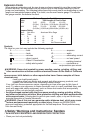
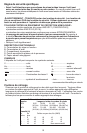
Be sure your power supply agrees with nameplate marking. 120 Volts AC only means
your tool will operate on standard 60 Hz household power. Do not operate AC tools on
DC. A rating of 120 volts AC/DC means that you tool will operate on standard 60 Hz AC or
DC power. This information is printed on the nameplate. Lower voltage will cause loss of
power and can result in over-heating. All Black & Decker tools are factory-tested; if this tool
does not operate, check the power supply.
Operating Instructions
WARNING: To reduce the risk of serious personal injury, read and follow all important
safety warnings and instructions prior to using this tool.
Switch
To turn the tool ON, hold it as shown in Figure 1 and push the portion of the switch marked
“I”. To turn the tool OFF, push the portion of the switch marked “O”.
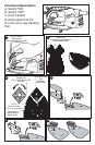
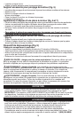
Operation (Figure 1)
Grasp product as shown in gure 1 and turn it on. NOTE: Do not rest fingers on platen
during use. Move it in long sweeping strokes across the surface, letting it do the work.
Light pressure is all that is required for sanding, polishing or scrubbing. Excessive
pressure will slow the tool and produce inferior results. Check your work often, product is
capable of removing material rapidly.
WARNING: Shock hazard. Under no circumstances should this product be used near
water.
CAUTION: To reduce the risk of injury, turn off and unplug the tool before making
any adjustments or removing or installing attachments or accessories.
Detail Sanding
Your tool is equipped with a teardrop base which allows you to use it on large flat surfaces
and tight spots or corners.
The pad tips may wear unevenly, depending on use. The pads are designed to allow you
to interchange and /or rotate the diamond tip.
Fitting sanding sheets (Fig. 2)
• Detachthetwodiamond-shapedtipsfromthesandingsheet.
• Holdthetoolwiththesandingbasefacingupwards.
• Placethesandingsheetontothesandingbase.
The diamond-shaped tip can be reversed and replaced when worn.
• Whenthefrontpartofthetipisworn,detachitfromthesheet,reverseitandpressitonto
the sanding base again.
• Whenthewholetipisworn,removeitfromthesandingbaseandfitanewtip.
Tip of the Sanding Base (Fig. 3)
When the sanding base tip is worn, it can be reversed or replaced.
• Reverseorreplacethewornpart.
Finger Attachment (Fig. 4)
The finger attachment is used for fine detail sanding.
• Removethescrew.
• Removethediamond-shapedtipholderfromthesandingbase.
• Fitthefingerattachmentontothesandingbase.
• Fitandtightenthescrew.
• Alignthesandingsheetwiththefingerattachment.
Contour Holder Attachment (Fig. 5)
• Thecontoursandingpiecesareforsandingcurvedsurfacesandgrooves.
• Removethescrew.
• Removethediamond-shapedtipholderfromthesandingbase.
• Fitthecontourholderontothesandingbase.
• Fitandtightenthescrew.
Fitting and Removing a Contour Piece (Fig. 6 & 7)
• Choosethecontoursandingpieceprofilemostsuitableforyourapplication.
• Placeoneendofthecontoursandingpieceintotherecessatthefrontendofthecontourholder.
7