


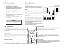


J4 J6 J7
J3
J8
J4 J6 J7
J4 J6 J7
J4 J6 J7
J4 J6 J7
1
(Highest)
2
3
4
(Lowest)
J8
J8
Enabled
Disabled
GATING
PRIORITY LEVEL
BUS
ASSIGNMENT
A
B
Mono
Both
J3
J3 J3
Bus
Gain
Provides control over the level of input signal that can be applied to the
internal signal buses of the main unit. Allows a way to balance the input lev-
els of various devices so that the main unit’s controls can be set to relatively
uniform or optimum levels.
Gate - Threshold (Thresh)
Controls the minimum necessary input signal level to turn the module’s out-
put on and apply signal to the main unit’s buses.Clockwise rotation increas-
es the necessary signal level required to produce output and mute lower
priority modules.
Gate - Duration (Dur)
Controls the amount of time the output and mute signal of the module
remains applied to the main unit’s buses after the input signal falls below the
required minimum signal level (set by the threshold control).
Ducking (Duck)
Controls the level of the output signal from the module when it has been
requested to mute it’s output.The range is adjustable from no reduction in
level to full muting of the output signal.
Line In Connection
Uses a standard RCA connector to make connections to the module’s input.
The input is quasi-balanced to reduce the chance of ground loops while still
being compatible with unbalanced signal sources.
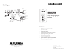
BUFFER
OUT
LINE
IN
THRESH
G
E
T
A
DUR
DUCK
GAIN
BRG1R
Jumper Selections
Bus Assignment
The module can be set to operate so that the mono signal
can be sent to the main unit’s A bus, B bus,or both buses.
Gating
Gating (turning off) of the module’s output when insuffi-
cient audio is present at the input can be disabled.
Detection of audio for the purpose of muting lower prior-
ity modules is always active regardless of jumper setting.
Priority Level
*
This module can respond to 4 different levels of priority.
Priority 1 is the highest priority, it mutes modules with
lower priorities and is never muted.Priority 2 can be muted
by priority 1 modules and mutes modules set for 3 or 4.
Priority 3 is muted by either priority 1 or 2 modules and
mutes priority 4 modules.Priority 4 modules are muted by
all higher priority modules.
* The number of priority levels available is determined by
the amplifier the modules are used in.
Module Installation
1. Turn off all power to the unit.
2. Make all necessary jumper selections.
3. Position module in front of desired module bay
opening, making sure that the module is right-
side up.
4. Slide module on to card guide rails. Make sure
that both the top and bottom guides are
engaged.
5. Push the module in to the bay until the faceplate
contacts the unit’s chassis.
6. Use the two screws included to secure the mod-
ule to the unit.
WARNING:
Turn off power to unit and make all jumper
selections before installing module in unit.
Buffer Out Connection
This RCA connector makes a buffered version of the Line In signal available
as a feed to other amplifier inputs.The output is quasi-balanced to reduce
the chance of ground loops while still being compatible with unbalanced
inputs.This output is not affected by module controls or muting functions.