


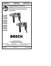

-7-
Operating Instructions
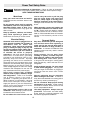
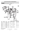
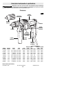
TRIGGER CONTROLLED VARIABLE SPEED
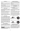
Your tool is equipped with a variable speed
trigger switch. The tool speed can be
controlled from minimum to maximum
nameplate rated RPM by the pressure you
apply to the trigger. Apply more pressure to
increase the speed and release pressure to
decrease speed (Fig. 1).
"LOCK-ON" BUTTON
The "Lock-ON" button, located in the handle
of your tool allows for continuous operation at
maximum RPM without holding the trigger.
TO LOCK TRIGGER "ON": squeeze trigger,
depress button and release trigger.
TO UNLOCK THE TRIGGER: squeeze trigger
and release it without depressing the "Lock-
ON" button.
If the “Lock-ON” button is
continuously being de-
pressed, the trigger can not be released.
REVERSING SWITCH BUTTON
The reversing switch button is located above
the trigger switch and is used to reverse
rotation of the bit. For forward rotation, (with
the chuck pointed away from you) move
button to the far left. For reverse rotation move
the button to the far right.
Do not change direction of
rotation until the tool comes
to a complete stop. Shifting during rotation of
the chuck can cause damage to the tool.
AUXILIARY HANDLE
The auxiliary handle will provide additional
control, support and guidance for the tool. The
handle is adjustable around the 360° handle
collar mount. To mount, loosen wing knob and
slide handle completely over chuck onto the
collar mount and tighten wing knob (Fig. 1).
!
WARNING
INSERTING BIT
For small bits, open jaws enough to insert the
bit up to the flutes. For large bits, insert the bit
as far as it will go. Center the bit as you close
the jaws by hand. This positions the bit
properly, giving maximum contact between
the chuck jaws and the bit shank.
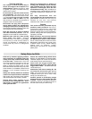
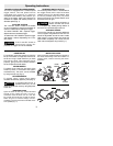
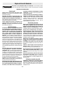
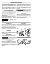
KEYED MODELS
To tighten chuck, insert key into each of the
three key holes in succession and tighten
clockwise firmly. The chuck can be released
by using one hole only (Fig. 2).
KEYLESS MODELS
To tighten chuck, rotate chuck sleeve
clockwise and securely tighten by hand (Fig. 3).
To prevent friction burns, or
possible hand injury, do not
loosen or tighten the chuck by using the power
of the drill.
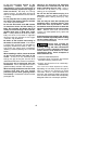
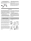
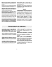
REMOVING CHUCK
Open the chuck all the way, remove left-hand
thread screw inside chuck by turning it
clockwise. Insert the short arm of a 3/8" hex
key wrench and close jaws on flats of wrench.
Strike long arm of wrench sharply counter-
clockwise, remove wrench and unthread chuck
from spindle (Fig. 4).
INSTALLING CHUCK
Always keep the spindle threads, the threads of
the chuck and securing screw free of debris. To
install a chuck, reverse “removing the chuck”
procedure.
!
WARNING
!
CAUTION
Counter
Clockwise
Clockwise
CHUCK
SLEEVE
Counter
Clockwise
Clockwise
CHUCK KEY
FIG. 2 FIG. 3
KEYED
KEYLESS
FIG. 4