


W
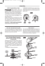
HEEL GUARD INSTALLATION
Wheel guard must be
attached when using disc
grinding wheels. Always keep wheel guard
between you and your work while grinding.
The position of the guard can be adjusted to
accommodate the operation being performed.
To attach wheel guard DISCONNECT tool
from power source.
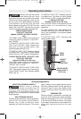
Position wheel guard on spindle neck so that
the arrow on guard lines up with the arrow on
the spindle neck. Rotate wheel guard
clockwise 90º until it clicks in place (Fig. 2).
TO ADJUST GUARD: depress guard release
button (Fig. 1), rotate guard to desired position,
release button and let it click in place.
T
O REMOVE GUARD: Depress release button,
rotate guard until arrow on guard lines up with
arrow on spindle neck, and remove guard from
spindle neck.
Assembly
-7-
LOCK NUT AND BACKING FLANGE
Your tool is equipped with a threaded spindle
for mounting accessories. Always use the
supplied lock nut (and backing flange) that
has same thread size as spindle.
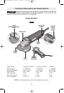
SIDE HANDLE
The side handle used to guide and balance the
tool can be threaded into the front housing on
either side of the tool, depending on personal
preference and comfort. Use the side handle
for safe control and ease of operation.
!
WARNING
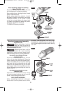
Disc Grinding Wheel Assembly
(Models 1810PD, 1810PSD, 1811PS &
1811PSD only)
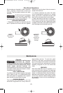
Disconnect tool from power source. Be sure
that wheel guard is in place for grinding.
Place BACKING FLANGE and GRINDING
WHEEL on the spindle. Thread on the lock
nut and tighten nut using the supplied lock
nut wrench, while holding the spindle lock in
(Fig. 3).
TO REMOVE: Reverse procedure.
LOCK NUT
TYPE 27
GRINDING
WHEEL
BACKING
FLANGE
SPINDLE
WHEEL
GUARD
SPINDLE
NECK
FIG. 2
GRINDING
WHEEL
LOCK NUT
SPINDLE
WHEEL
GUARD
BACKING
FLANGE
FIG. 3
BM 1609929J65 02-08 2/20/08 11:30 AM Page 7