


-11-
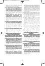
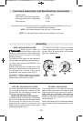
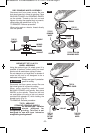
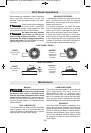
DISC GRINDING WHEEL ASSEMBLY
Disconnect tool from power source. Be sure
that wheel guard is in place for grinding. Place
BACKING FLANGE and GRINDING WHEEL
on the spindle. Thread on the lock nut and
tighten nut using the supplied lock nut wrench,
while holding the spindle lock in (Fig. 3).
TO REMOVE: Reverse procedure.
When using spin-on wheels, thread directly
onto the spindle.
LOCK NUT
TYPE 27
GRINDING
WHEEL
BACKING
FLANGE
SPINDLE
TYPE 27
GRINDING
WHEEL
LOCK NUT
SPINDLE
TYPE 27
WHEEL GUARD
BACKING
FLANGE
FIG. 3
TYPE 27 SPIN-ON
GRINDING WHEEL
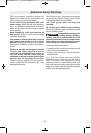
ABRASIVE TYPE 1A & 27A
WHEEL ASSEMBLY
Using the optional type 1A wheel guard, it is
possible to perform limited cutting on small
stock such as metal tubes, piping or rebar.
Do not attempt to cut large stock or sheets of
metal as this tool is not designed to be a
dedicated cutting tool.
Always use type 1A protection
guard for cutting.
Disconnect tool from power source. Be sure
that wheel guard is in place for cutting.
When using mounting wheels, thread
BACKING FLANGE onto spindle, then place
WHEEL on the spindle. Thread on the lock
nut and tighten nut using a lock nut wrench
provided with adapter kit, while holding the
spindle lock in (Fig. 4).
TO REMOVE: Reverse procedure.
TYPE 1 ABRASIVE
STRAIGHT GRINDING WHEELS
Do not use type 1 abrasive
wheels designed for
straight/die grinding. This tool is not
designed for use with type 1 abrasive
straight/die grinding wheels.
!
WARNING
!
WARNING
TYPE 1A
WHEEL GUARD
SPINDLE
BACKING
FLANGE
TYPE 1A
(ISO41)
CUTTING
WHEEL
FIG. 4
LOCK NUT
TYPE 27A
CUTOFF
WHEEL
BM 1609929Y07 10-10:BM 1609929Y07 10-10 1/18/11 10:06 AM Page 11