


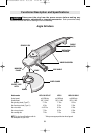
Grinder Assembly
-7-
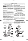
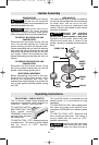
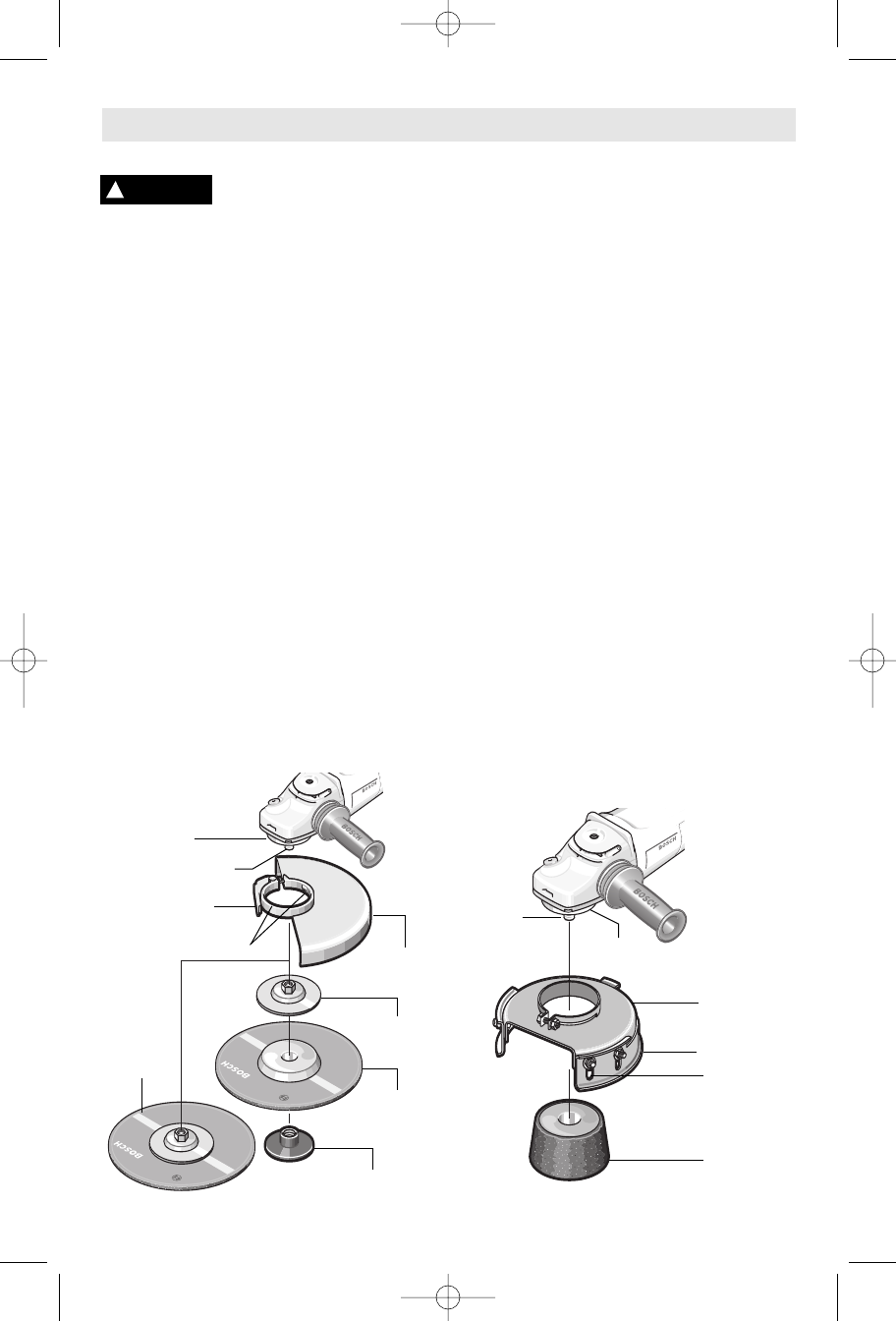
WHEEL GUARD INSTALLATION
U
se wheel guard with disc
grinding wheels. Always
close the latch to secure the guard. Keep the
guard between you and the wheel. Do not
direct guard opening toward your body.
The position of the guard can be adjusted to
accommodate the operation being performed.
To attach wheel guard DISCONNECT tool
from power source.
Open guard release/lock latch and position
guard on spindle neck so that the two bumps
on guard, line up with the two notches on the
spindle neck.
Rotate guard either direction to desired
position, and close latch to secure guard in
place.
TO REMOVE GUARD: Open guard
release/lock latch, rotate guard until the two
bumps on guard line up with the two notches
on the spindle neck, and lift guard off the
spindle neck.
LOCK NUT AND BACKING FLANGE
Your tool is equipped with a threaded spindle
for mounting accessories. Always use the
lock nut and backing flange that has same
thread size as spindle.
DISC GRINDING WHEEL ASSEMBLY
Disconnect tool from power source. Be sure
that wheel guard is in place for grinding.
When using spin-on grinding wheels, thread
d
irectly onto the spindle.
When using mounting wheels, thread
BACKING FLANGE onto spindle, then place
GRINDING WHEEL on the spindle. Thread
on the lock nut and tighten nut using a lock
nut wrench provided with adapter kit, while
holding the spindle lock in.
TO REMOVE: Reverse procedure.
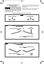
CUP GRINDING WHEELS
Use cup grinding wheels for heavy-duty stock
removal of metals, concrete and stone.
ADJUSTABLE CUP
WHEEL GUARD INSTALLATION
Open the guard clamp and fit it on the
mounting flange then secure by tightening
the clamp screw. ALWAYS HAVE THIS
GUARD ATTACHED WHEN USING CUP
GRINDING WHEELS
The adjustable guard allows you to lower or
raise the guard’s shell. TO ADJUST: Loosen
the four bolts on the shell, and secure the
shell for 1/4” wheel exposure for maximum
safety.
ATTACHING CUP GRINDING WHEEL
Thread the cup grinding wheel on the spindle
shaft CLOCKWISE. Press in the spindle lock
button and turn the cup grinding wheel until
the lock button engages, then tighten the
wheel securely by hand.
TO REMOVE: Reverse procedure.
!
WARNING
BACKING
FLANGE
LOCK NUT
WHEEL
GUARD
DISC
GRINDING
WHEEL
SPIN-ON
GRINDING
WHEEL
SPINDLE
MOUNTING
FLANGE
BUMPS
GUARD
RELEASE / LOCK
LATCH
BOLT
ADJUSTABLE
GUARD
CUP
GRINDING
WHEEL
SHELL
SPINDLE
MOUNTING
FLANGE
BM 1609929H54 08-06 8/3/06 11:44 AM Page 7