


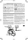
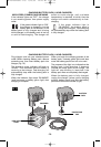
ATTACHING NON-MARRING OVERSHOE
Your tool is equipped with a protective plastic
overshoe that protects finer surfaces.
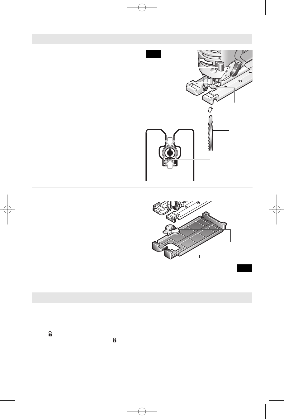
To attach, hook overshoe over front of metal
footplate and snap into place at rear of
footplate (Fig. 3).
ANTI-SPLINTER INSERT
To minimize splintering of the top surface of
the material being cut, place the anti-splinter
insert in the blade opening of the footplate, or
the non-marring overshoe.
Note: This insert will only work with blades
that have ground sides such as T301CD,
TB1B, T101D, and T101DP.
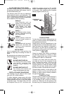
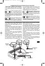
SWITCH LOCK
The switch lock is designed to prevent
accidental starts. To operate switch, press the
switch lock button with your thumb to the
unlock symbol. To lock the switch, press the
switch lock button to the lock symbol
(Fig. 1).
VARIABLE SPEED CONTROLLED
TRIGGER SWITCH
Your tool is equipped with a variable speed trigger
switch. The tool can be turned "ON" or "OFF" by
squeezing or releasing the trigger. The speed
can be adjusted from the minimum to maximum
nameplate SPM by the pressure you apply to the
trigger. Apply more pressure to increase the
speed and release pressure to decrease speed
(Fig. 1).
BRAKE
When the trigger is released it activates the
electrical brake to stop the blade quickly. This
feature is especially useful when making
repetitive cuts.
Operating Instructions
-8-
Assembly
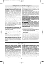
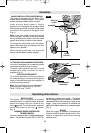
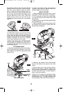
BLADE INSTALLATION AND REMOVAL
This jigsaw is equipped with the Bosch “Clic”
t
ooless blade changing system. This system
m
akes changing blades simple and fast.
Insert the saw blade (teeth in cutting
direction) until it latches in the plunger. When
inserting the saw blade, the back of the blade
must rest in the groove of the guide roller
(Fig. 2).
Note: If the saw blade cannot be inserting
into the plunger, the slots of the blade holder
are not positioned as shown, push the blade
ejector lever briefly to the front and release.
To change the saw blade, push the ejector
lever to the center stop; this releases the saw
blade and it is ejected.
When changing the blade, tool should be
held so that the blade is safely ejected.
FIG. 2
EJECTOR
LEVER
BLADE
FOOTPLATE
ANTI-SPLINTER
INSERT
NON-MARRING
OVERSHOE
GUIDE
ROLLER
FIG. 3
PLUNGER
GUIDE
ROLLER
BM 2610925943 6-05 6/10/05 10:25 AM Page 8