


-7-
Operating Instructions
ON/OFF AND VARIABLE
SPEED SWITCHES
Your Sander is equipped with a variable
speed switch and a separate on/off switch.
The speed can be controlled from minimum
to maximum speed by moving the switch
lever to desired setting.
TO TURN TOOL “ON”: Slide switch to the
“ON”position (I) on symbol.
TO TURN TOOL “OFF” Slide switch to the
“OFF” position (0) off symbol.
TO INCREASE SPEED: Move variable speed
control lever toward the + sign.
TO DECREASE SPEED: Move variable speed
control lever toward the – sign.
Setting
Material/Application
Low Delicate surfaces, veneers,
or light surface finishing &
polishing
Low Plastics or other soft surfaces
Medium Solid wood, fast stock
removal, paint removal
High General use, metal sanding &
finishing, chipboard, coarse
sanding on rough surfaces,
& polishing
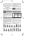
SELECTING A CONTOUR SHAPE
Individual contour shapes are available in three
basic styles. A variety of radiuses are available
in each style:
Convex shapes: 1/8", 3/16", 1/4", 3/8", 1/2",
5/8"
Concave shapes: 1/8", 3/16", 1/4", 3/8", 1/2",
5/8"
Angled shapes: Flat, 30°, 60°, 45°, 90°, -90°
The contour shapes are available in a variety of
different radiuses to match common
configurations. Additionally, each contour can
be modified or customized by trimming or
shaping the material to the desired form.
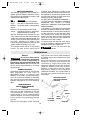
INSTALLING AND REMOVING DETAIL
PAD & OPTIONAL SHUTTER PAD
Your sander is equipped with a quick change
clamping mechanism that allows you to easily
change accessories without additional tools.
To attach detail pad or optional shutter pad to
the sander:
1. Disconnect sander from power source.
2. Rotate red release lever to lower the
accessory clamp holder.
3. Apply hook and loop backed sandpaper to
pad.
4. Insert pad completely into the top and
back of the holder until it reaches the rear
"stop".
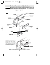
HINT: Make sure the small grip dimples have
firmly secured the rubber grip ring (Fig. 1).
5. Press holder firmly back up into place
until the pad "snaps" into position.
To remove pad, rotate lever to release and
lower the clamp holder. Remove the pad
from the holder. You are now ready to install
another pad or contour shape.
When using detail sanding pads, regularly
rotate the pad 180 degrees to maximize all
surfaces for longer, more efficient use.
INSTALLING AND REMOVING
CONTOURS
To attach a contour shape to the sander:
1. Disconnect sander from power source.
2. Rotate red release lever to lower the
accessory clamp holder.
3. Apply either a sanding tube or pressure
sensitive adhesive directly to contour shape.
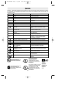
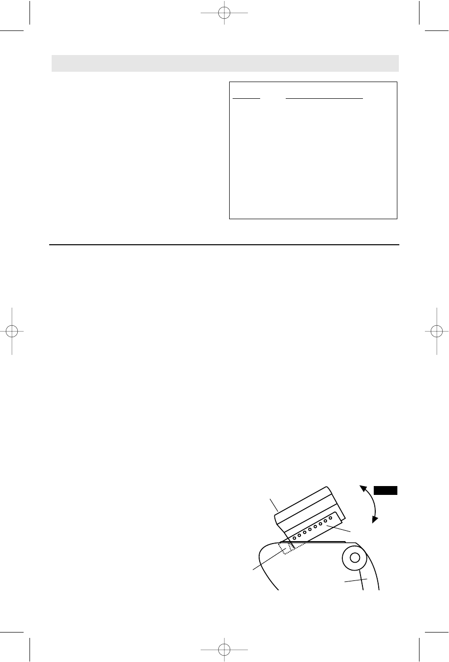
4. Insert contour completely into the top and
back of the holder until it reaches the rear
"stop" (Fig. 2).
CONTOUR
REAR
STOP
RELEASE LEVER
CLAMP
HOLDER
FIG. 2
DM 2610919361 9/03 9/5/03 8:33 AM Page 7