


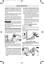
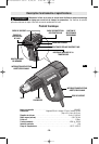

SETTING THE AIR FLOW
The air flow can be regulated with the air flow
button (Fig. 1).
Minimum air flow (approx. 3.6-8.8 CFM,
depending on temperature setting)
Maximum air flow (approx. 17.6 CFM)
The CFM at each of the 10 airflow settings
depends on the temperature setting. For
example, at the lowest temperature (120
degrees) the lowest airflow setting delivers 3.6
cfm, whereas at the highest temperature (1200
degrees) the lowest airflow setting delivers 8.8 cfm
The air flow can be increased by pressing the
“+” side of the air flow button or decreased by
pushing the “–” side of the button. Brief
pressing of the button increases or decreases
the air flow by one step. Longer pressing of the
button increases or decreases the air flow
continuously until the maximum or minimum air
flow is reached.
Decrease the air flow when, for example:
The surroundings of the workpiece should not
be heated more than necessary. A light
workpiece could be blown away by the air
stream.
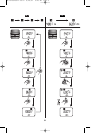
PROGRAMMED OPERATION
In programmed operation, air flow and
temperature settings can be stored in four
programs. In each program, any air flow and
temperature combination are possible.
Also in programmed operation, air flow and
temperature can be changed at any time. If the
changes are not stored through
reprogramming, they are lost when switching
the unit off or when changing to another
program.
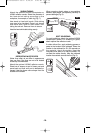
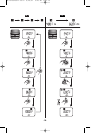
To use one of the pre-stored modes, press the
program selection button
“P” until the number
of the required program ( , , or ) as
shown in the display (Fig. 2).
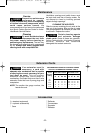
PRE-STORED PROGRAMS
The unit is equipped with the following four pre-
stored programs:
Program
Application
Temperature
Air
Flow
1 Shaping of plastic 480 °F
tubing (e.g. LDPE)
2 Welding of plastic 660 °F
(e.g. PVC)
3 Removing paint/ 860 °F
softening adhesives
4 Soldering 1000 °F
REPROGRAMMING
Press the program selection button “P” until
the number of the program to be
reprogrammed is shown in the display. Set the
required temperature and air flow (see figure 3).
As soon as the values of the program are
altered, the symbol blinks in the upper left of
t
he display.
After setting the required air flow and
temperature, press the store button (for about
5 seconds) until the symbol in the display
disappears. The values set are now stored
under the program number shown in the
display.
NORMAL OPERATION
To change to normal operation, press the
program selection button
“P” repeatedly until
there is no longer a program number shown
over the temperature in the display.
The air flow and temperature can be changed
at any time.
The last set unprogramed values for the air flow
and temperature remain stored under the
following conditions:
– Move to program operation
– Move to the cool setting
– Switch-off the unit
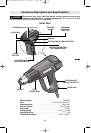
REMOVING THE HEAT PROTECTOR
For working in especially narrow places, the
heat protector can be removed.
Be careful of the hot nozzle!
Increased danger of burning
exists when working without the heat protector.
To remove or mount the heat protector, the unit
must be turned off and have cooled. To cool
unit down, run unit briefly in the cool air setting,
if necessary.
Turn the heat protector counter-clockwise to
remove, and clockwise to mount again.
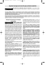
USING THE UNIT IN
STATIONARY POSITION
For cooling of the heated unit or to have both
hands free for working, the unit can be set
down in the upright position on the stand legs
on the rear of the tool (Fig. 6).
Be especially careful when
working with the upright unit!
There is danger of burning by the hot nozzle
and the hot air stream.
-8-
!
WARNING
!
WARNING
BM 1619929572 08-07 8/28/07 9:45 AM Page 8