


-7-
Assembly
Preparing the Saw
BLADE SELECTION
No one blade can be efficient on all cutting
jobs. Different materials require specially
designed blades. Since your reciprocating saw
can cut so many materials, many types of
BOSCH blades are available. Be sure to use
the proper blade to insure proper cutting
performance.
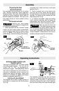
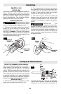
INSTALLING A BLADE
Unplug tool from power
source before changing blade
or making any adjustments.
1. Insert the blade into the LockJaw™ blade
holder until the locking collar automatically
rotates clockwise and locks the blade in place
(Fig. 2).
Note: if the blade will not lock
automatically, rotate the locking collar counter-
clockwise until it clicks and locks in the open
position (Fig. 3).
2 Push in and pull out on the blade to be
sure the pin in the clamp housing goes
through the hole in the blade to hold the blade
securely. The blade may be inserted with the
teeth facing down or up.
3. To remove the blade, rotate the locking
collar counter-clockwise and the blade will
automatically eject from the LockJaw™ blade
holder and lock the collar in the open position.
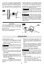
Make sure that the front end
of the blade extends through
the footplate for the entire stroke length. Do
not use specialty blades that are very short or
those with a significant cant. Blade must not
contact footplate. A blade which is too short or
canted could jam inside the foot and snap.
!
WARNING
FIG. 3
!
WARNING
FIG. 2
Operating Instructions
Open
Position
LockJaw
™
BLADE HOLDER
LOCKING
COLLAR
BLADE
LOCKING
COLLAR
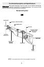
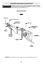
VARIABLE SPEED CONTROLLED
TRIGGER SWITCH
Your tool is equipped with a variable speed
controlled trigger switch. The tool can be
turned "ON" or "OFF" by squeezing or
releasing the trigger. The blade plunger stroke
rate can be adjusted from the minimum to
maximum nameplate stroke rate by the
pressure you apply to the trigger. Apply more
pressure to increase the speed and release
pressure to decrease speed (Fig. 1).
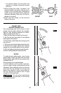
FOOTPLATE ADJUSTMENT
The footplate tilts in order to keep as much of
its surface in contact with the work surface
Fig. 4 (a).
The footplate assembly can also be locked
into one of three projection positions to
optimize blade life and/or to reduce blade
protrusion beyond the end of the footplate,
such as when cutting into large diameter pipe
FIG. 4
(a)
(b)