


3
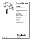
Installation S19-220
Bradley Corporation • 215-158 Rev. W; ECN 08-503 2/4/08
Installation
Supplies Required:
• (3) 3/8” wall fasteners and bolts
• Pipe sealant
• Piping to 1/2” NPT water supply inlet on unit
• Piping to 1-1/4” NPT drain outlet for eyewash
• Sign-mounting hardware
NOTE: Local codes may require the installation
of a backfl ow prevention valve to complete proper
installation. Compliance with local codes is the
responsibility of the installer. Valve must be tested
annually to verify that it is functioning properly.
Backfl ow prevention valves are not included with
the fi xture and may be supplied by the contractor
or purchased from Bradley Corporation.
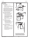
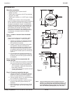
Step 1: Install inlet drain fitting
NOTE: The top of the eyewash heads should be
33”–45” (838mm–1143mm) from the floor.
1. Position the inlet drain fitting over the
1-1/4” drain outlet pipe from wall.
2. Using the inlet drain fitting as a template,
mark the bolt hole locations on wall OR
install three suitable fasteners (supplied
by installer) for 3/8” bolts in the wall at the
marked hole locations.
3. Bolt the inlet drain fitting to the wall or wall
fasteners using 3/8” bolts (supplied by
installer).
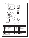
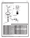
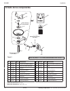
Step 2: Assemble components
1. Assemble the remaining eyewash
components as shown on page 4.
• Apply pipe sealant (supplied by installer) to
all male-threaded pipe joints.
• Use a strap wrench around pipes when
tightening to prevent pipe marring.
Step 3: Connect water supply
1. Connect the water supply piping to the 1/2”
NPT inlet on the eyewash (piping supplied by
installer).
2. Connect the tailpiece to the 1-1/4” NPT drain
outlet on the eyewash.
3. Mount the safety sign to the wall using sign-
mounting hardware (supplied by installer).
4. Open the water supply lines. Test for leaks
and adequate water flow.
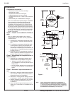
NOTE: All dimensions assume standard thread
engagement. Variations in manufacturing allow for
+/- 1/8 (3mm) per threaded joint. To fi nd the tolerance
of a dimension, add the number of thread joints in
between a dimension and multiply it by 1/8 (3mm).
36" (914mm)
Suggested
Height
To Floor
4-1/2"
(114mm)
8-1/4"
(210mm)
30-1/2"
(775mm)
Suggested
Height
To Floor
Wall
15-1/2" (394mm)
7-3/8"
(187mm)
2-1/4"
(57mm)
5-1/4"
(133mm)
7-1/4"
(184mm)
4"
(102mm)
Ø 5/16"
(8mm)
13-1/4"
(337mm)
Ø 10" (254mm)