


Page 1
MODEL 744SFL
HUMIDITY SENSING RECESSED
FLUORESCENT FAN / LIGHT
READ AND SAVE THESE INSTRUCTIONS
CLEANING &
MAINTENANCE
Installer: Leave this manual
with the homeowner.
To clean trim ring / baffle: Vacuum with a
soft brush attachment or remove trim ring /
baffle and clean with a soft cloth.
SENSOR CLEANING
The humidity sensor is mounted in the trim
ring/baffle. The sensor will operate most
reliably when cleaned occasionally as follows:
1. Disconnect power at service entrance.
2. Remove the trim ring/baffle. Use a dry
dustcloth, clean toothbrush, or lightly
vacuum to clean sensor and grille.
DO NOT USE ABRASIVE CLOTH,
STEEL WOOL PADS, OR SCOURING
POWDERS.
3. DO NOT USE cleaning sprays, solvents,
or water on or near the sensor!
To clean inside of housing: Remove trim
ring / baffle and vacuum inside of housing
with a soft brush attachment.
Motor is permanently lubricated. Do not oil or
disassemble motor.
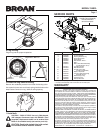
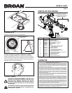
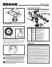
See “Service Parts” section for a list and
illustrations of service parts.
OPERATION
The light, fan and humidity control can be operated
together or independently using multi-function switch
wall controls.
• Use a 3-function control to independently operate
light, fan and humidity control.
• Use a 2-function control to independently operate
light and humidity control. For fan operation see
MANUAL ON WITH TIMED OFF section below.
• Use a 2-function control to independently operate
light and fan. Wire humidity control direct to insure
humidity control is always on.
See “Connect Wiring” section for various wiring options.
Do not use a dimmer switch control to operate
light, fan or humidity control.
SENSOR OPERATION
This humidity-sensing
fan responds to: (a) rapid to
moderate humidity increases and (b) humidity above
a 50%-100% relative humidity set-point. (a) and (b)
are set with “SENSITIVITY” adjustment. Fan may
occasionally turn on when environmental conditions
change. If the fan continuously responds to changing
environmental conditions, “SENSITIVITY” adjustment
may be required (see section below).
STATUS INDICATOR
This indicator can only be seen by looking directly at it.
Normal mode is 5-seconds on and off. If it blinks rapidly
for 5-seconds and then off, check sensor connections
on trim ring/baffle and fan housing.
MANUAL ON WITH TIMED OFF
For odor or vapor control, the fan can be energized
by cycling its wall-mounted switch if one is installed.
Once the fan has been turned on in this manner, it will
remain on for the set “TIMER” period.
To manually energize the fan:
1. Go to Step 2 if switch is already on; otherwise,
turn switch on for more than 1 second.
2. Switch off for less than 1 second.
3. Switch back on and fan will turn on.
SENSITIVITY ADJUSTMENT
“SENSITIVITY” has been factory set for most
shower applications. If the fan is in a tub area or is
used for dampness control, the “SENSITIVITY” may
need to be increased toward maximum (“MAX.”).
If the control is responding too often to changing
environmental conditions, adjustment toward less
(“MIN.”) “SENSITIVITY” may be required. To adjust
the “SENSITIVITY”:
1. Turn power off at electrical service panel.
2. Remove bulb.
3. Through trim ring/baffle, locate the “SENSITIVITY”
screwdriver slot.
4. Using a small, flat-blade screwdriver, carefully
rotate “SENSITIVITY” adjustment clockwise
toward “MAX.” or counterclockwise toward “MIN.”
5. Re-install bulb.
6. Turn power on and check operation by turning
on shower or other humidity source until fan
turns on.
7. Repeat above steps if necessary.
TIMER ADJUSTMENT
This humidity-sensing fan has a “TIMER”. It is user-
adjustable from 5 to 60 minutes and is factory-set
at 20 minutes. The “TIMER” controls how long the
fan remains on (a) after rise in humidity and (b)
humidity level are both below the user-adjustable
“SENSITIVITY” setting or after being energized by
cycling power switch.
To adjust the “TIMER”:
1. Disconnect power at electrical service panel.
2. Remove bulb.
3. Through the trim ring/baffle, locate the
“TIMER” screwdriver slot.
4. Using a small, flat-blade screwdriver, carefully
rotate “TIMER” adjustment clockwise
to increase time or counterclockwise to
decrease time.
5. Re-install bulb.
6. Turn power on and check operation by cycling
power switch as instructed under “MANUAL
ON WITH TIMED OFF” or by turning on a
humidity source until fan turns on.
7. Check “TIMER” setting with watch or clock
after turning humidity source off if it was
turned on it Step 6.
8. Repeat above steps if necessary.
!
CAUTION
1. For general ventilating use only. Do not use
to exhaust hazardous or explosive materials
and vapors.
2. To avoid motor bearing damage and noisy and/
or unbalanced impellers, use the cardboard
protector (provided) to keep drywall spray,
construction dust, etc. off power unit.
3. The fluorescent bulb used with this product
inserts straight into the bulb socket. Do not
attempt to insert or remove bulb by twisting it.
4. Please read specification label on product for
further information and requirements.
WARNING
TO REDUCE THE RISK OF FIRE, ELECTRIC
SHOCK, OR INJURY TO PERSONS, OBSERVE
THE FOLLOWING:
1. Use this unit only in the manner intended by the
manufacturer. If you have questions, contact the
manufacturer at the address or telephone number
listed in the warranty.
2. Before servicing or cleaning unit, switch
power off at service panel and lock the service
disconnecting means to prevent power from
being switched on accidentally. When the service
disconnecting means cannot be locked, securely
fasten a prominent warning device, such as a tag,
to the service panel.
3. Installation work and electrical wiring must be
done by a qualified person(s) in accordance with
all applicable codes and standards, including
fire-rated construction codes and standards.
4. Sufficient air is needed for proper combustion
and exhausting of gases through the flue
(chimney) of fuel burning equipment to prevent
backdrafting. Follow the heating equipment
manufacturer’s guideline and safety standards
such as those published by the National Fire
Protection Association (NFPA), and the American
Society for Heating, Refrigeration and Air
Conditioning Engineers (ASHRAE), and the local
code authorities.
5. When cutting or drilling into wall or ceiling,
do not damage electrical wiring and other
hidden utilities.
6. Ducted fans must always be vented to
the outdoors.
7. Never place a switch where it can be reached
from a tub or shower.
8. Do not use a dimmer switch to operate the light
in this unit.
9. Install this unit in a flat ceiling only.
10. For use in non fire rated installations only.
11. Not for use in environmental air handling spaces.
12. If this unit is to be installed over a tub or shower, it
must be marked as appropriate for the application
and be connected to a GFCI (Ground Fault Circuit
Interrupter) - protected branch circuit.
13. Do not install in a ceiling thermally insulated to a
value greater than R40.
14. This unit must be grounded.