


Sequential Multi-Stage Charging Overview
Upon applying AC power to your ProSport On-Board Marine Battery Charger, the
following will be observed:
The Blue AC Power LED will illuminate followed by the Red Charging LED and Red Battery Type
LED (Factory setting for Flooded (Lead-acid)/AGM batteries). The combination of these three LED’s
turning on indicates ProSport has started its Sequential Multi-Stage Charging process. When the
Charge Process is completed, only the Green READY and Blue AC Power LEDs will be illuminated.
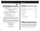
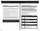
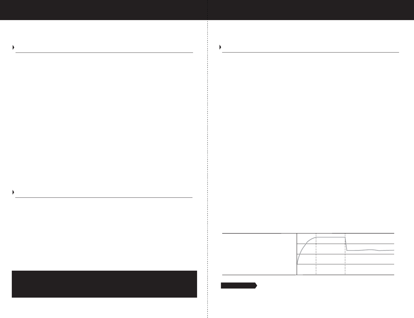
ProSport’s Sequential Multi-Stage Charging process delivers three sequenced modes of
operation that include: Charging, Conditioning and Maintenance of each battery. This process
is proven to extend the life of your batteries and will fully charge your batteries each time.
Stage 1: ProSport Charging
During this mode, the ProSport will use its available charging amps (as controlled
by temperature) until battery voltage is raised to 14.6 VDC (Factory setting for
Flooded (Lead-acid) / AGM batteries).
Stage 2: ProSport Conditioning
The ProSport will hold batteries at 14.6 VDC (Factory setting for Flooded (Lead-acid) / AGM
batteries) providing a 100% charge to each battery, while conditioning batteries by desulfating
each battery. Upon completion, the ProSport will go to into its maintenance mode.
Stage 3: ProSport Ready / Maintenance Mode
During this mode, the Red Charging LED and the RED Battery Type LED (Factory
set charge profile for Flooded (Lead-acid / AGM Batteries) will turn off indicating
the Charge Process is completed, followed by the Green READY LED turning On.
The Green READY LED and the Blue AC POWER LED will remain on indicating that your
batteries are fully charged and are being maintained with a precision 13.4 Volts DC
Finishing Voltage (Factory set charge profile for Flooded (Lead-acid / AGM Batteries).
ProSport’s Ready/Maintenance Mode is perfect for short or long term storage and will
never overcharge your batteries.
Note: Only the Green READY LED and the Blue AC POWER LED will remain on when
the ProSport is in its Ready/Maintenance Mode.
Performance Tip: For long term or winter storage/ maintenance of batteries, ProMariner
recommends that every 30 days: AC power is removed by unplugging your extension cord at the
GFCI outlet first, check battery electrolyte levels. Re-apply AC power to your ProSport Charger.
This practice will properly maintain your batteries resulting in extended battery life and use.
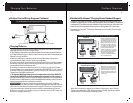
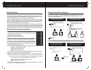
ProSport DC Output Cable Wiring Diagrams-Typical Installations
Note: ProSport Waterproof On-Board Marine Battery Chargers are designed for any combination
of Group 24,27,30 and 31 batteries. Each Battery Charger DC output cable must be connected
to one (1) 12 Volt DC battery (even if batteries are configured for 24 Volt DC or 36 Volt DC trolling
Motor or System Applications). See typical wiring diagrams for these systems on page 10.
ProSport Dual Bank Models can charge (2) independent or parallel 12 Volt DC Batteries or
a 24 Volt DC Bank Configuration of: (two 12 Volt DC batteries in series) and our ProSport
Triple Bank Model can charge (3) Independent or parallel 12 Volt DC batteries or a 36 Volt
DC configuration of: (three 12 Volt DC batteries in series). Please see our typical wiring
diagrams for 24 Volt DC and 36 Volt DC bank configurations and more. Simply attach each
battery charger DC output cable to one 12 Volt battery. Because each output is isolated, all
parallel or series jumper wires can remain connected to your batteries. Specifically you do
not have to remove series or parallel jumper cables to use your ProSport Charger.
Note: If your application is for 4D or 8D large capacity batteries, please refer to
ProMariner's website www.promariner.com and view our ProTech-i and ProNautic
C3 Line of Dry Compartment Chargers. Using our online selector guide choose a
model that best fits your application for this class of batteries.
14
13
12
11
14.6V
13.4V
Charging Conditioning Maintenance / Float Mode
Average Voltage
Volts DC
6
ProSport Overview
9
Installation Guidelines
Installation (Continued)
7. Run your cables free from sharp objects and hold each of them in place with cable
ties. Coil excess cable, do not cut or shorten the length of the cables, as there are
in-line fuses located 4 inches from the end of each red (positive) cable. In addition,
there are fuses in all but one of the yellow (negative) leads. These fuses are in place
to protect the charger and output cables in the event of a short or reverse polarity.
8. Connect the DC output cables as illustrated on page 10. Make sure the (yellow)
wires are connected as illustrated to the negative side of the battery and the red
wires are connected to the positive side of the battery.
9. Make sure all DC connections are correct, tight, and free from corrosion.
10. Locate the AC power cord in an open-air area of your boat at least 21 inches
from the charger, batteries, and fuel fill lines.
11. Connect a heavy duty UL approved extension cord to the ProSport Charger first.
After connecting the extension cord to the charger, proceed to plug the extension
cord to a nearby 120VAC GFCI protected (Ground Fault Circuit Interrupt) outlet.
Always remove the extension cord from the 120VAC outlet first when charging is
completed, followed by unplugging the charger.
You are now connected and charging your batteries. View the LED indicators.
Assuming your batteries are discharged you should observe: Blue AC POWER LED
is turned on, followed by the Red Charge LED and RED Battery Type LED turning on
(red is the factory setting of flooded (Lead-acid)/AGM type batteries .