


FP202800, FP202900
3
www.chpower.com
Operating Instructions and Parts List
Introduction (Continued)
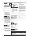
Pressure Switch (located
internally)- When the compressor
is turned ON, this switch will shut
compressor off automatically when
tank pressure reaches maximum shut-
off / cut-out pressure. If compressor
remains on and air is depleted from
tank, this switch will allow compressor
to automatically restart at the restart /
cut-in pressure.
Regulator - The regulator controls
the amount of air pressure released at
the hose outlet. Turning the regulator
knob clockwise (to the right) will
increase air pressure at the outlet.
Turning the knob counter-clockwise
(to the left) will lower air pressure to
the outlet. Turning knob fully counter-
clockwise will shut off flow of air
completely.
Pressure Gauges - There are two
gauges located next to the regulator.
These gauges read air pressure in
pounds per square inch (psi) The larger
gauge shows pressure at the outlet.
Make sure this gauge reads ZERO
(by adjusting the regulator) BEFORE
changing air tools or disconnecting
hose from outlet. The small gauge
shows pressure in the tank indicating
compressor is building pressure
properly.
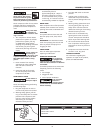
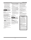
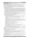
GROUNDING INSTRUCTIONS
1. This product is for use on a
nominal 120 volt circuit and has a
grounding plug that looks like the
plug illustrated in Figure 3. Make
sure the product is connected
to an outlet having the same
confi guration as the plug. This
product must be grounded. In
the event of an electrical short
circuit, grounding reduces risk of
electrical shock by providing an
escape wire for electric current.
This product is equipped with a
cord having a grounding wire
with an appropriate grounding
plug. Plug must be plugged into
an outlet that is properly installed
and grounded in accordance with
all local codes and ordinances.
ASME Safety Valve - This valve
automatically releases air if the tank
pressure exceeds the preset maximum.
Handle - Designed to move the
compressor.
Drain Valve - This valve is located on
the bottom of the tank. Use this valve
to drain moisture from the tank daily
to reduce the risk of corrosion.
Installation
LOCATION
It is extremely important to use the
compressor in a clean, well ventilated
area where the surrounding air
temperature will not be more than
100°F.
A minimum clearance of 18 inches
between the compressor and a wall
is required because objects could
obstruct air flow.
Do not locate the
compressor
air inlet near steam, paint spray,
sandblast areas or any other source
of contamination. This debris will
damage the motor.
Figure 2
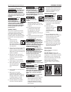
TEST
RESET
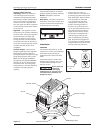
Figure 3 - Grounding Method
Grounded
Outlet
Grounding
Pin
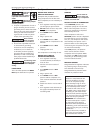
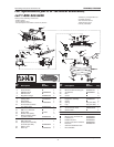
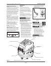
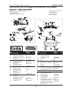
Figure 4
Regulator
Tank Gauge
Regulator Gauge
Handle
ASME Safety Valve
Tank Drain Valve
ON / OFF Switch
Shroud
Tank