


Operating Instructions and Parts List
4
www.chpower.com
FP202801, FP202901
Installation
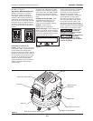
LOCATION
It is extremely important to use the
compressor in a clean, well ventilated
area where the surrounding air
temperature will not be more than
100°F.
A minimum clearance of 18 inches
between the compressor and a wall
is required because objects could
obstruct air flow.
Do not locate the
compressor
air inlet near steam, paint spray,
sandblast areas or any other source
of contamination. This debris will
damage the motor.
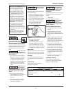
GROUNDING INSTRUCTIONS
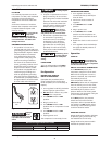
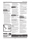
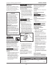
1. This product is for use on a
nominal 120 volt circuit and has a
grounding plug that looks like the
plug illustrated in Figure 4. Make
sure the product is connected
to an outlet having the same
confi guration as the plug. This
product must be grounded. In
the event of an electrical short
circuit, grounding reduces risk of
electrical shock by providing an
escape wire for electric current.
This product is equipped with a
cord having a grounding wire
with an appropriate grounding
plug. Plug must be plugged into
an outlet that is properly installed
and grounded in accordance with
all local codes and ordinances.
Improper
use of
grounding plug can result in
a possible risk of electrical
shock!
Do not use a
grounding adapter
with this product!
2. If repair or replacement of cord or
plug is necessary, do not connect
grounding wire to either fl at blade
terminal. The wire with insulation
having an external surface that
is green (with or without yellow
stripes) is the grounding wire.
Never connect
green (or green
and yellow) wire to a live terminal.
3. Check with a qualifi ed electrician
or serviceman if grounding
instructions are not completely
understood, or if in doubt as
to whether product is properly
grounded. Do not modify plug
provided; if it will not fi t outlet,
have proper outlet installed by a
qualifi ed electrician.
Overheating, short
circuiting and fi re
damage will result from inadequate
wiring.
LUBRICATION
This is an oilless product and DOES
NOT require lubrication to operate.
Pre-Operation
BEFORE FIRST START-UP
BREAK-IN PROCEDURE
(Complete this procedure before
using compressor for the first time.
Once completed, it is not necessary to
repeat.)
1. Turn regulator knob fully clockwise
(to the right) to open air fl ow.
2. Do not attach a hose or any other
fi tting to the compressor.
3. Turn ON / OFF switch to OFF
position.
4. Plug in power cord.
5. Turn ON / OFF switch to ON
position and run compressor for 30
minutes.
6. Turn ON / OFF switch to OFF
position.
7. Unplug power cord.
The compressor is now ready for use.
BEFORE EACH START-UP
OPERATING PROCEDURE
1. Turn regulator knob fully
counterclockwise (to the left) to
close air fl ow.
2. Connect air hose to outlet of
regulator.
3. Turn ON / OFF switch to OFF
position.
4. Plug in power cord.
5. Turn ON / OFF switch to ON
position and let compressor run
until it reaches automatic shutoff
pressure.
6. Attach tire chuck or tool to end of
hose.
7. Turn regulator knob clockwise (to
the right) to desired pressure of
tool being used.
Operation
START-UP
Do not attach air
tools to open end
of the hose until start-up is completed
and the unit checks OK.
ON / OFF CYCLING OF COMPRESSOR
In the ON / AUTO position, the
compressor pumps air into the tank.
When a shut-off (preset “cut-out”)
pressure is reached, the compressor
automatically shuts off.
If the compressor is left in the
ON / AUTO position and air is depleted
from the tank by use of a tire chuck,
tool, etc., the compressor will restart
automatically at its preset “cut-in”
pressure. When a tool is being used
continuously, the compressor will cycle
on and off automatically.
In the OFF position, the pressure
switch cannot function and the
compressor will not operate. Make
sure switch is in OFF position when
connecting or disconnecting power
cord from electrical outlet.
PRESSURE GAUGES
Gauge attached to regulator indicates
air pressure going to hose (and any
tool attached to end of hose).
Gauge attached to pressure switch
indicates air pressure in tank.
TEST
RESET
Figure 4 - Grounding Method
Grounded
Outlet
Grounding
Pin
Minimum Gauge of Extension Cords
Length of Cord 25 feet 50 feet 100 feet
Gauge 14 12 10