


3
HL540200
www.chpower.com
Introduction
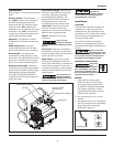
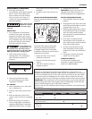
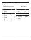
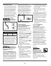
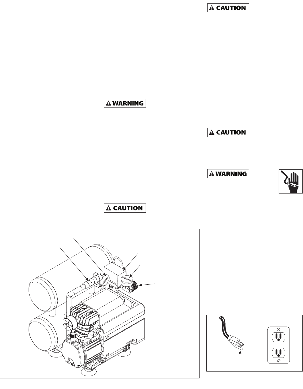
Refer to Figure 1 to locate the following
items.
Pressure Switch - Auto/Off Switch - In
the "AUTO" position, the compressor
shuts off automatically when tank
pressure reaches the maximum preset
pressure. In the "OFF" position, the
compressor will not operate. This switch
should be in the "OFF" position when
connecting or disconnecting the power
cord from the electrical outlet.
Regulator - The regulator controls
the amount of air pressure at the hose
outlet.
ASME Safety Valve - This valve
automatically releases air if the tank
pressure exceeds the preset maximum.
Exhaust Tube - This tube carries
compressed air from the pump to the
check valve. This tube becomes very hot
during use. To avoid the risk of severe
burns, never touch the discharge tube.
Outlet Pressure Gauge - Will show
air pressure at the outlet in pounds per
square inch (psi). Make sure this gauge
reads ZERO (by adjusting regulator
knob fully counterclockwise) before
changing air tools or disconnecting air
hose from outlet.
If the overload
protector is
actuated, the motor must be allowed
to cool down for approximately 30
minutes before it will reset.
Installation
LOCATION
It is extremely important to install the
compressor in a clean, dry, and well
ventilated area. The compressor must
be placed on a firm, level surface where
the surrounding air temperature will
not be more than 100°F.
A minimum clearance of 18 inches
between the compressor and a wall is
required because objects could obstruct
air flow.
Do not locate the
compressor air inlet
near steam, paint spray, sandblast areas
or any other source of contamination.
This debris will damage the motor.
ELECTRICAL INSTALLATION
All wiring
and
electrical connections should
be performed by a qualified
electrician. Installation must
be in accordance with local codes and
national electrical codes.
WIRING
1. Local electrical wiring codes
differ from area to area. Source
wiring, plug and protector must
be rated for at least the amperage
and voltage indicated on motor
nameplate, and meet all electrical
codes for this minimum.
2. Use a slow blow fuse or a circuit
breaker.
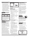
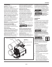
3. This product is for use on a nominal
120 volt circuit and has a grounding
plug that looks like the plug
illustrated in Figure 2.
Tank Pressure Gauge - Will show air
pressure in tank while the compressor
is running, indicating compressor
is building pressure properly. This
gauge will show maximum pressure
of compressor when it shuts off
automatically at the pressure switch.
Check Valve - One-way valve that
allows air to enter the tank, but
prevents air in the tank from flowing
back into the compressor pump.
Handle - Designed to move the
compressor.
Never use the
handle on wheeled
units to lift the unit completely off the
ground.
Drain Valve - This valve is located on
the bottom of the tank. Use this valve
to drain moisture from the tank daily to
reduce the risk of corrosion.
Motor Reset - (not shown, located
inside motor). Designed to keep the
motor from overheating. The motor has
an auto reset protector. To reset once
the motor has cooled, turn the pressure
switch to the OFF position, then to the
AUTO position.
This compressor is
equipped with an
overload protector which will shut off
motor if it becomes overloaded.
TEST
RESET
Figure 2 - Grounding Method
Grounded Outlet
Grounding Pin
Figure 1 - Unit Identification
Handle
Pressure Switch
(AUTO / OFF)
Regulator
Tank Pressure Gauge
Outlet Pressure Gauge